CDR Explained

hce

So can i....
Joined
Nov 10, 2009
Posts
1,143
Reaction score
396
Location
Glasgow MT (Official middle of nowhere)
I like this diagram.

Shows the twisted path the air has to take through the cdr. The rapid change in direction will cause some oil vapor to hit the side of the cdr and condense. The condensed oil collects on the bottom of the cdr. As enough collects it will eventually run over 1/4" protrusion and drain back down as it clings to the side of the tube.
 

junk

Full Access Member
Joined
May 25, 2006
Posts
1,773
Reaction score
63
Location
Paullina, IA
Yeah the S1600 uhaul truck I had had an air compressor and the oil return for it went through the front of the block in that location. Good to know.
 

f-two-fiddy

Registered User
Joined
Mar 22, 2004
Posts
2,960
Reaction score
5
Location
Duluth, Mn.
I need to know more about this drain. I will plumb my Walker Air Sep return there, if it's large enough!
 

RLDSL

Diesel fuel abuser
Joined
Dec 14, 2005
Posts
7,701
Reaction score
22
Location
Arkansas
One of the common things I've seen is questions about what exactly the CDR valve is and what it does. Also, it seems pretty common for a "bad cdr" to be looked to for a cause of excessive oil consumption which makes little sense once you understand the working of the unit. My intent here is to shed a little light on the unit.

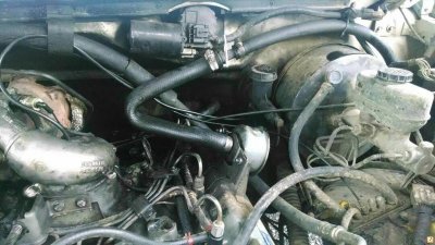
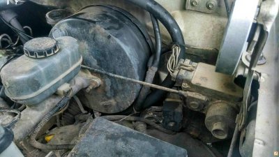
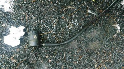
First of all, the question is what is a cdr valve? CDR stands for crankcase depression regulator. It's the can located on the back of the intake on a stock motor and mounted on the valve cover or the air box in turbo motors. Physically it's about 4" diameter and 1 1/2" thick with a 1" hole in the front face of the can going to the intake and a ~1" tube coming from the bottom of the can going to the valley pan. Functionally it's the link between the crankcase and the intake and serves to vent crankcase vapors (blowby with a small amount of vaporized oil) into the intake so that they're burned. This is similar in function to the PCV system on a gasser, but rather different in implementation due to the design of a diesel.

From my Ford 'Diesel Engine Operations' training manual:

"Some engines use a more complicated [than a simple tube from the crankcase to the intake] crankcase emissions system with a crankcase depression regulator. In this system, crankcase vapors must go through the crankcase depression regulator to get into the intake system. This device is designed to maintain pressure in the crankcase as close to atmospheric pressure as possible. A high vacuum in the crankcase will tend to draw dirt from the outside through the front and rear seals. This will result in shortened seal life. In addition, high crankcase pressure may cause lube oil to be forced out of the gaskets and seals resulting in leaks."

It is interesting that high vacuum sucking up oil causing a runaway is not mentioned as a reason for fitting the CDR system. Also note that minimizing oil consumption is not mentioned.

On a gasser the PCV system connects into the intake side of the throttle, so there is always going to be a vacuum on one side of the PCV valve. For the reasons mentioned above, it's strongly desirable to maintain nearly atmospheric pressure in the crankcase. The PCV valve thus acts as a regulator to block the crankcase off from the high intake vacuum, especially under closed throttle. Typical intake vacuum on a gasser is 15-20 inhg.

In contrast, the intake on a diesel is under a minimum of vacuum, at least as long as the inlet is free flowing. There is a slight vacuum, but it's minimal. From what I can find, this is typically ~5 in h20 (note the different units) with a healthy air filter. Of note, IH specifies a max of 25 in h20 air filter restriction. This is equal to ~0.9 psi or ~1.8 in hg. That is, the absolute max worst case plugged air filter operating condition is some 20 times less intake vacuum than a gasser. A more normal full throttle operating condition would be ~0.1 psi/0.2 in hg of vacuum. This is somewhat less than the vacuum you creating sucking soda up a straw at mcdonalds.

So now let's look at the inside of this puppy.....

You must be registered for see images attach


Its very simple - exactly 2 parts within the can, a spring and a diaphragm. The port of the front of the can connecting to the intake extends ~1in into the can and has a flat end. The spring goes around this, and the diaphragm is the diameter of the overall can, sealed around the edges and has a steel plate at the center against which the spring bears and which fits against the intake port tube if you compress the spring. There is a small (~1/16") hole drilled in the rear cover to vent the back side of the diaphragm to the atmosphere. The spring is fairly weak, requiring only 1.3 lb to compress far enough for the diaphragm plate to seal against the intake tube.

Note the absence of any fancy oil separators or filtration stuff. Also note that the tube leading to the valley pan protrudes ~1/4" into the can, so there is no easy drain path for any accumulated oil to drain back to the crankcase.

Based on the construction, we can establish the functioning of the valve. With the back side of the diaphragm vented to atmosphere, the position of the diagram is going to be a function of the pressure within the can. A vacuum (relative to the outside atmosphere) is going to pull the diaphragm closed against the spring tension eventually closing off the intake port completely once a high enough vacuum is reached. Based on the size of the can and spring tension, a vacuum of ~3 in h20 within the can would cause the diaphragm to close off the port. Note however, that this *does not* mean that a 3 in vacuum in the intake closes it. The can connects to both the crankcase and the intake, and the crankcase pressure is always going to be higher than the intake due to blowby. So the pressure within the can is going to be higher than the intake vacuum. Exactly by how much is a a complex function of the flow rates and restrictions within the crankcase, but it's safe to conclude that valve is going to maintain crankcase pressure somewhere around 2 in h20 of vacuum.

Now remembering the above discussion, the normal operating vacuum of your intake is 2-5 in h20 if you have a healthy filter, so the CDR really does very little in normal operation. It's only really going to come into play with a clogged air filter or some other restriction.

Note the extreme simplicity of the valve - there is very little to wear out. Possibly the diaphragm could fail, or a very remote possibly of the spring breaking. A more likely failure would be for the vent port on the back of the valve to get plugged with paint or debris. Even then though, the effect of this failure is going to be pretty minimal unless you're running around with a horrible air filter.

So in conclusion, there is very little reason why one should need to replace a CDR valve, nor is there likely to be any issues running a road draft tube provided it doesn't cause crankcase pressure to be too high.

Further, there is no reason for the CDR to have anything to do with oil consumption. The only exception would be a bad CDR combined with another problem, ie a clogged air filter.

In support of this I note that nowhere in any of my extensive tech manual reading have I seen any mention of a maintenance requirement to change the CDR valve, nor any indication that one should look to it for an oil consumption problem.

My IH manual lists the following possible reasons for high oil consumption:
-Towing extremely heavy loads
-Improper operation, ie using the wrong gear range
-Plugged air cleaner
-Worn valve guides
-Worn piston rings

So bottom line, don't waste your money.
~John

Nice theory and all, but you have to remember. THeres a LOT of things that manuals leave out because they are not written for laymen, they are written for professional mechanicas, who are supposed to know things that regular folks generally dont, like the fact that these type of breather systems werent just used on the IH engines ore even the GM engines, but lots of CAT and other engines. and they all perform the same basic function of allowing a crankcase to breathe., and anytime you have a malfunction with the factory design in a factory crancase scavanging system, you WILL get oil consumption issues, I dont care WHAT kind of engine it is. Those other little functions listed are just added functions of the cdr, not its ONLY functions. When they list functions like that in a manual it is to inform the mechanics on the line as to what possible NEW things this system might be doing ALONG with the normal designed function of the basic system on the vehicle that all certified line mechanics would be very familiar with.. These breather systems are designed on systems that some of us have been working with since road draft tubes were all factory equipment breathers on big engines and some of us have a slightly better understanding on how these things really work in the real world.
 

jaluhn83

Full Access Member
Joined
May 19, 2012
Posts
1,597
Reaction score
49
Location
Upper Marlboro, MD
I like this diagram.

Shows the twisted path the air has to take through the cdr. The rapid change in direction will cause some oil vapor to hit the side of the cdr and condense. The condensed oil collects on the bottom of the cdr. As enough collects it will eventually run over 1/4" protrusion and drain back down as it clings to the side of the tube.

It's really not at all twisted, it's very straight - straight up tube and into the intake tube. Not even really that tight of a turn.

The way an oil separator would be designed is to have one or more tight 180* degree turns, preferably from a vertically down direction to vertically up. Any suspended oil will get flung to the outside of the air stream due to momentum, hit the surfaces of the baffles and condense. You also need an independent oil drain to the sump below oil level to allow an uninterfered return flow for the condensed oil.

Having oil try to flow back down the same tube as the air is flowing up just leads to the oil getting atomized and thrown back up into the CDR valve. This is demonstrated by the issues that were mentioned above with a bypass filter return going into the same area as to crankcase vent.
 

PwrSmoke

Full Access Member
Joined
Jan 2, 2007
Posts
807
Reaction score
23
Location
Northwest Ohio
RLDSL: When I read what you quoted above, I was left with his main point being, "If you have oil consumption problems, don't necessarily or arbitrarily replace the CDR as the first step."
 

jaluhn83

Full Access Member
Joined
May 19, 2012
Posts
1,597
Reaction score
49
Location
Upper Marlboro, MD
Tell us what you plan to do with the four ports... one for oil temp perhaps? Had my head not been up my ******, I would have added a port for that purpose when I had the engine apart... . I even had the bung sitting there read to go! Brain flatulence, I guess. I used to have a dipstick tube oil temp test device, which I swapped around to different engines, but it was old and finally died a few years ago... though not before I did a bunch of testing on the 6.9L. Learned some interesting things... but that's another tale.

Actually these are in addition to the oil temp gauge port I put in last time around...

One is for another oil temp sensor. The current sensor is for an isspro gauge, the other one will be a homemade sensor based around an LM34. The LM34/35 are single chip sensor systems that output a fixed 10 mv/degree output, so you can get a temp reading easily by just hooking up a voltmeter. I'm planning to use them for a number of temp measurements which will all be routed to a display panel with a selector switch and also some circuitry to run warning lights and cooling pumps. With the fixed voltage output it's fairly simple to make a warning system or a thermostatic control system using a voltage comparator. Could also do something using a programmable microcontroller that would be more elegant, but also more complex to build.

I'm also planning to eventually setup a auxiliary oil cooler using a air to oil cooler and a small pump, so 2 are the suction/return ports for that.

Also looking at building an oil separator system for the PCV probably with one on each valve cover, so one port on each side of the pan for that.

Finally thinking of using a bypass oil filter, so that's another thing that needs a port.

Not sure if or when all these would actually happen, but I'm putting the ports in anyway while I can.

Will have pictures one of these days once I get it cleaned up and painted. Still waiting for the 1/8" flange for the oil level sensor to come in.


You must be registered for see images attach
[/QUOTE]
 

jaluhn83

Full Access Member
Joined
May 19, 2012
Posts
1,597
Reaction score
49
Location
Upper Marlboro, MD
Nice theory and all, but you have to remember. THeres a LOT of things that manuals leave out because they are not written for laymen, they are written for professional mechanicas, who are supposed to know things that regular folks generally dont, like the fact that these type of breather systems werent just used on the IH engines ore even the GM engines, but lots of CAT and other engines. and they all perform the same basic function of allowing a crankcase to breathe., and anytime you have a malfunction with the factory design in a factory crancase scavanging system, you WILL get oil consumption issues, I dont care WHAT kind of engine it is. Those other little functions listed are just added functions of the cdr, not its ONLY functions. When they list functions like that in a manual it is to inform the mechanics on the line as to what possible NEW things this system might be doing ALONG with the normal designed function of the basic system on the vehicle that all certified line mechanics would be very familiar with.. These breather systems are designed on systems that some of us have been working with since road draft tubes were all factory equipment breathers on big engines and some of us have a slightly better understanding on how these things really work in the real world.

I don't disgree with your main point, however some points of discussion......

The manual I quote from is a basic into level tech manual intended for beginning students - it's not written for professional mechanics. No where in any of my reference, professional mechanic or otherwise do I see anything relating the CDR valve to oil consumption. There is documentation that high or low crankcase pressure can cause problems, but not that the CDR valve is a maintenance item or any sort.

I agree that tampering with the PCV system can cause problems, but not that any deviation from design *will* cause problems, nor that "wear" or "failure" of the CDR valve will cause them in an otherwise functional engine.

I do not have much personal experience with other makes of heavy/medium duty engines, so I cannot say how other systems are setup.

"Scavenging system" is to me a misleading term though I am not sure it was meant that way. There is no scavenging going on here - that is, there is no forced ventilation of the crankcase. Instead the system merely provides a path for crankcase gasses to vent to.

The only difference between a RDT and the CDR system is where the gasses wind up. The only reason they went to the CDR system was for emissions.

I do not doubt that you sir may have vastly more experience working on and with engines. I only base my thoughts on what I have experience with and what I see in the design of the system. It may very well be that I am wrong and a bad CDR causes oil consumption. However, I would submit that this is not due to the CDR itself, but rather a band aid fix for a deeper problem.

With respect, I must ask what part of your background and training gives you "a slightly better understanding of how these things really work"? Do you have any references? I must admit that I personally was not involved in the engineering of these engines, so I cannot with certainly say how the design was intended.
 

hce

So can i....
Joined
Nov 10, 2009
Posts
1,143
Reaction score
396
Location
Glasgow MT (Official middle of nowhere)
Having oil try to flow back down the same tube as the air is flowing up just leads to the oil getting atomized and thrown back up into the CDR valve. This is demonstrated by the issues that were mentioned above with a bypass filter return going into the same area as to crankcase vent.[/QUOTE]

If you have that much blowby going up the cdr to pull oil off the sides your engine is shot.
 

RLDSL

Diesel fuel abuser
Joined
Dec 14, 2005
Posts
7,701
Reaction score
22
Location
Arkansas
RLDSL: When I read what you quoted above, I was left with his main point being, "If you have oil consumption problems, don't necessarily or arbitrarily replace the CDR as the first step."

Oh so true. THere are many reasons for excess crankcase pressure, and just as many cures, but, a failed breather system WILL result in excess oil consumption, which is something very basic in any engine design and the op is stating that it will not .

The internet is full of misinformation, this shouldnt be the place to spread it. Before I retired and closed up shop, I cant count the number of vehicles that I had to replace entire computer/sensor systems because of the rumor that has spread through the interned over dielectric grease being used on electronic terminals where folks would run out and slather dielectric grease all over their electronic terminals in an attempt to *protect* them after reading this tripe all over the internet ( which in fact causes resistance and ends up over time causing cascading electronic failures ). This kind of amature misinformation ends up causing folks lots of money and grief in the long run. I could go on and on all day over the kinds of things like that that have made the rounds by well meaning folks who end up causing countless aggravation around the world in an attempt to prove a theory

Aside from the fact that breather function is a known fact, there are enough folks right here on OB who have experienced first hand the results of a failed CDR and what happens when it is replaced to know that oil consumption is related. I would hate to think what would happen if a bunch of folks would start ignoring replacing CDRs when oil consumption issues started popping up... then not long after they wound up having to pull transmissions to replace blown out rear main seals and worse.
 
Last edited:

Black dawg

Registered User
Joined
Jan 9, 2006
Posts
4,462
Reaction score
1,041
Location
sw mt
"Scavenging system" is to me a misleading term though I am not sure it was meant that way. There is no scavenging going on here - that is, there is no forced ventilation of the crankcase. Instead the system merely provides a path for crankcase gasses to vent to.

There actually is scavenging taking place especially on a healthy (low blowby engine). A simple test, remove oil filler with engine running and note amount of blowby, now remove air filter and do same test.

I also think that the cdr diaphragm moves more than we think, I had one that would get stuck shut (this took awhile to figure out and actually prove) so this one was moving a lot.
 

Black dawg

Registered User
Joined
Jan 9, 2006
Posts
4,462
Reaction score
1,041
Location
sw mt
"Scavenging system" is to me a misleading term though I am not sure it was meant that way. There is no scavenging going on here - that is, there is no forced ventilation of the crankcase. Instead the system merely provides a path for crankcase gasses to vent to.

There actually is scavenging taking place especially on a healthy (low blow by engine). A simple test, remove oil filler with engine running and note amount of blow by, now remove air filter and do same test.

I also think that the cdr diaphragm moves more than we think, I had one that would get stuck shut (this took awhile to figure out and actually prove) so this one was moving a lot.
 

tapdancewilly

Full Access Member
Joined
Dec 3, 2013
Posts
63
Reaction score
0
Location
Sisters Oregon
So just got this truck. It was set up with a road draft tube I believe its called. It had that filter on it which seems to be a irrigation filter haha. Except it leaks oil really bad! I want to put it back to normal and have it run into the intake. But I am concerned because all the oil that it leaked, I don't want that in the intake obviously. So this must have something to do with a messed up CDR right?

Sent from my XT1055 using Tapatalk
 

Attachments

  • uploadfromtaptalk1387079530769.jpg
    uploadfromtaptalk1387079530769.jpg
    111.4 KB · Views: 19
  • uploadfromtaptalk1387079540203.jpg
    uploadfromtaptalk1387079540203.jpg
    100.2 KB · Views: 19
  • uploadfromtaptalk1387079551486.jpg
    uploadfromtaptalk1387079551486.jpg
    116.2 KB · Views: 20
  • uploadfromtaptalk1387079567547.jpg
    uploadfromtaptalk1387079567547.jpg
    214.8 KB · Views: 21

IDIBRONCO

IDIBRONCO
Joined
Feb 5, 2010
Posts
14,976
Reaction score
14,078
Location
edmond, ks
I learned from my experience as a civilian contractor in Iraq that the Army wants the CDR on their HMVEE's replaced at every service interval. After reading this again, I realize that it's just a waste of money. I guess no one ever accused the Army of being a "for profit" organization!
 

jaluhn83

Full Access Member
Joined
May 19, 2012
Posts
1,597
Reaction score
49
Location
Upper Marlboro, MD
tapdancewilly,

The CDR will have absolutely nothing to do with the amount of oil coming out of the road draft tube. It's pretty normal to have a small amount of oil coming out of the rdt - unless it's enough to leave puddles under the truck when you park it should be fine to route into the inlet.

Also, the way that system is setup now is suboptimal because the hose is kinked coming off the cdr - that's going to restrict flow and could cause high crankcase pressure leading to oil leakage out the shaft seals/gaskets.
 
Top