6.9 IDI valve train questions + head gasket job

8769bigred

Registered User
Joined
Nov 5, 2024
Posts
53
Reaction score
31
Location
Portland Oregon
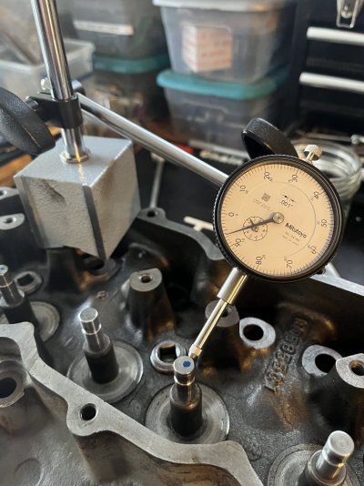
Ok so I went back to the drawing board for the valve guide measurements. I ditched my harbor freight dial indicator and got a good one. Iv slowing been buying Mitutoyo measuring tools over the years and now I had a need for a primo dial indicator. It worked ALOT better.

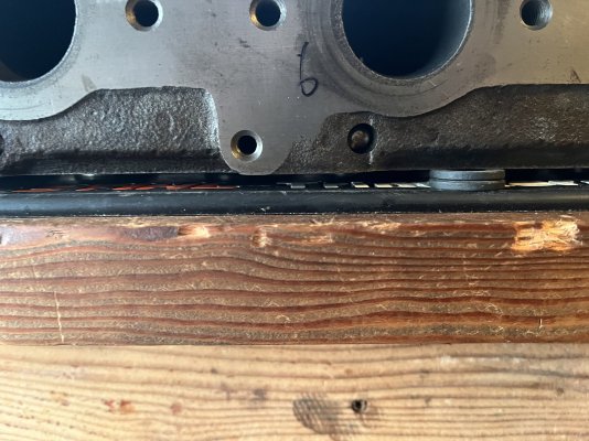
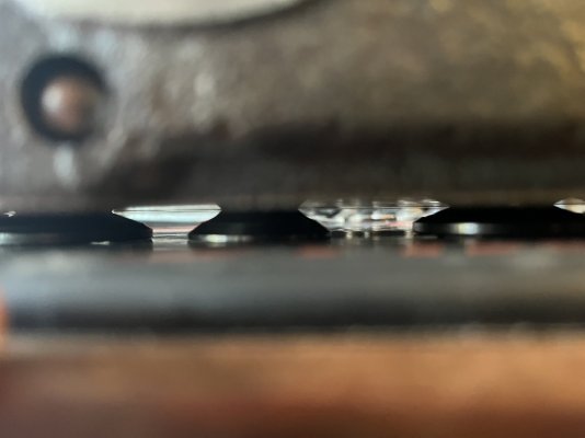
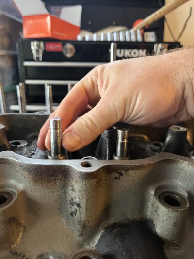
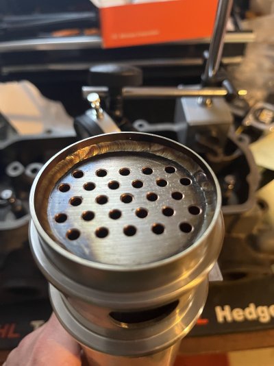
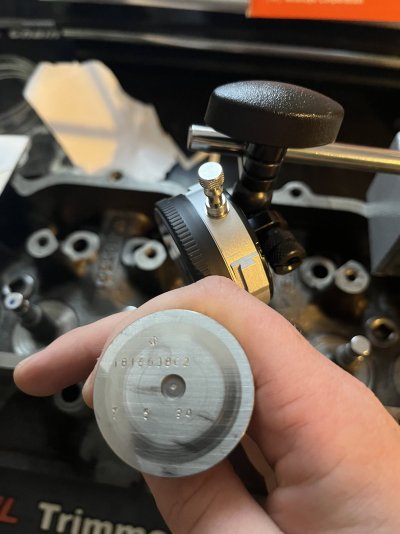
I also devised a strategy to deal with not having the ford valve stem spacer tool. I spaced the head off my bench with flat washers to give the valves more room to drop. I spaced the valves down into the guides to the point where the wear marks were no longer visible. I then measured all the guides the same way. Push valve towards indicator and zero. Pull valve straight towards me and record, divide value by 2.

This seemed to be a better strategy than leaving the heads flat on the bench. This method allowed the valves to walk in the guide more. I’m not sure if this is as far down as the ford tool lets the valves go. If I had the valves LOWER than the ford tool would allow my measurements should show more wear than I actually have.

I also feel like it’s easier to do consistent repeatable results compared to the hole gauge method.

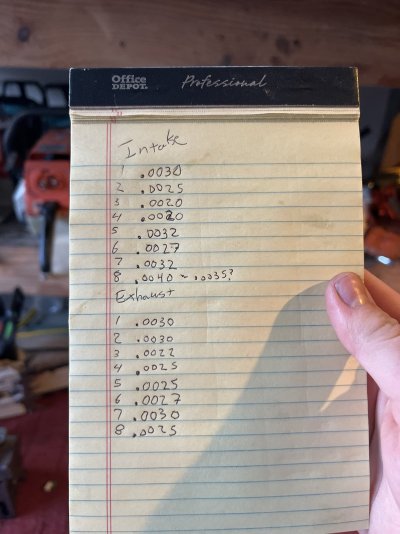
Based of my results I think my guides are good to go. I had one suspicious intake valve that I had a hard time getting a good read on. Some times .0035 some times .004. This is close to the .0055 wear limit.

Here’s my results for the rest of the guides
 

Attachments

  • IMG_9071.jpeg
    IMG_9071.jpeg
    313.8 KB · Views: 4
  • IMG_9069.jpeg
    IMG_9069.jpeg
    355.4 KB · Views: 4
  • IMG_9070.jpeg
    IMG_9070.jpeg
    157.3 KB · Views: 4
  • IMG_9068.jpeg
    IMG_9068.jpeg
    275.9 KB · Views: 4
  • image.jpg
    image.jpg
    256.5 KB · Views: 4

asmith

Full Access Member
Joined
Jan 28, 2012
Posts
833
Reaction score
375
Location
Atascadero, Ca
This method makes sense to me, but that really doesn't mean much. I have never done this, or looked into how its supposed to be done. But it seems to me you have a good repeatable test that gives you results across all the holes that can be compared with out too many variables.
Besides that, in my line of work, construction, we don't deal with tolerances that small, really the smallest I deal with is 1/32, maybe 1/64 on important things. most is in the 1/16-1/8 range.
 

8769bigred

Registered User
Joined
Nov 5, 2024
Posts
53
Reaction score
31
Location
Portland Oregon
@asmith thanks for the thoughts!! I think it’s as good of a method I can come up with ,without the tool. I need to upload a photo of the tool for future readers. Iv scoured the internet but not luck finding one. I think I’m going to give the guides a clean bill of health. One less machining process for me to pay for and one less process for the machine shop to screw up.
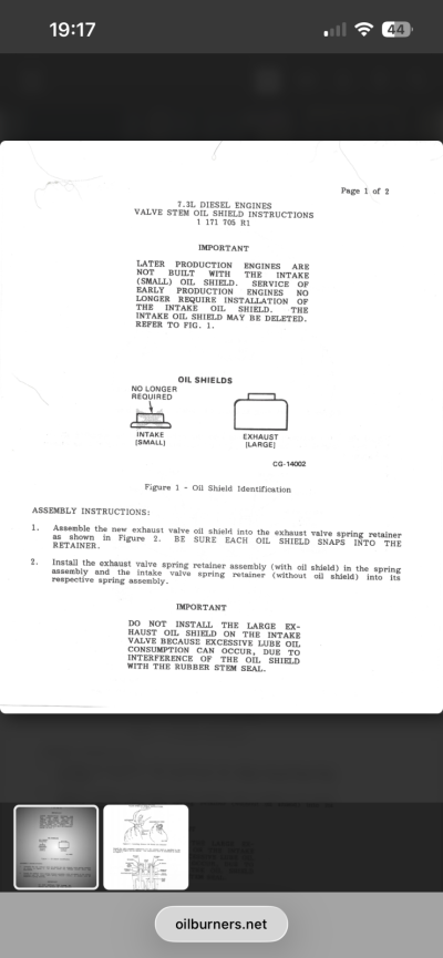
For future readers here is the photo of the ford tool that sets the valve opening distance before taking the dial indicator reading. Here is the literature as well.

You must be registered for see images attach
 
Last edited:

8769bigred

Registered User
Joined
Nov 5, 2024
Posts
53
Reaction score
31
Location
Portland Oregon
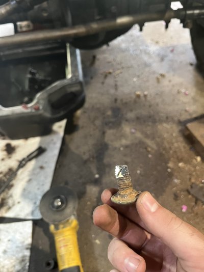
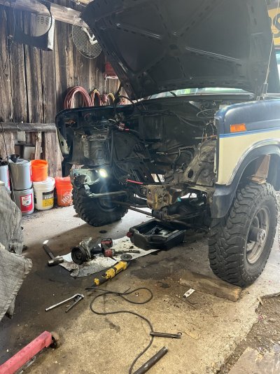
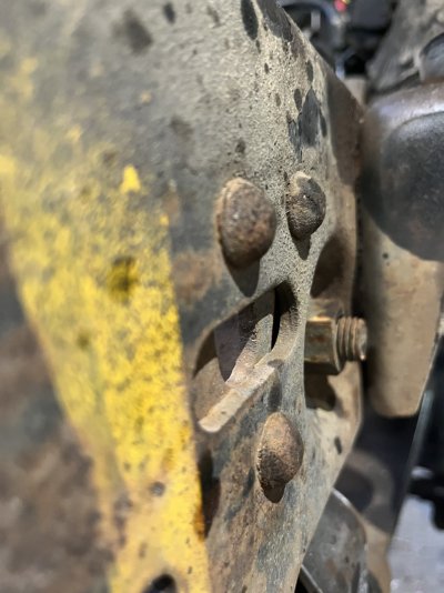
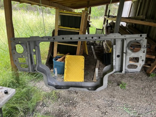
Not much has happened this week so far on the project. Iv been working on every thing but the motor. Prepping the new core support, drilling out loose leaf spring hanger rivets and cutting core support mounts out. Also going to re seal the P/S pump and replace the lines while I’m here.

I’m waiting on my 8th new exhaust valves. The eBay seller had a mix up and sent me 7 correct valves and one incorrect. Once I have the valve the heads will go to the machine shop.
 

Attachments

  • IMG_9087.jpeg
    IMG_9087.jpeg
    209.7 KB · Views: 8
  • IMG_9086.jpeg
    IMG_9086.jpeg
    477.8 KB · Views: 7
  • IMG_9088.jpeg
    IMG_9088.jpeg
    265.3 KB · Views: 8
  • IMG_9031.jpeg
    IMG_9031.jpeg
    632.5 KB · Views: 7

8769bigred

Registered User
Joined
Nov 5, 2024
Posts
53
Reaction score
31
Location
Portland Oregon
While I'm waiting on parts and machine work for this project, I thought this would be a good time to talk about the parts needed for a head gasket job / re seal


First off Gaskets.

I went with CDD full seal kit

The head gasket is branded with Fel-pros logo and seems to be of good quality. The gasket set also comes with Ford RTV, a Ford thermostat and a valley pan gaskets. It includes oil cooler O-Rings and all other gaskets. They seem to be of good quality. The oil cooler O-rings are said to be Ford but they are not the green color typically seen. The front seal that comes in the kit is a viton spring type manufactured by National. The rear main is a PTFE type seal most likely manufactured by FELPRO

On the topic of main seals, you will need sleeves for the crank in the rear and the balancer in the front.

Front Damper Sleeve is a National 99248
Rear crank sleeve is a SKF 99372

A word of caution on the rear main seal repair sleeve. It is difficult to correctly install the traditional wear sleeve with the crank in the motor. There is not enough clearance to remove the driver cap tab from the wear sleeve. I learned this the hard way and documented it in this thread on 'The Bullnose Forum' at this link

https://bullnoseforum.com/topic/12353-69-idi-rear-main-seal-leakinstallation/

I'm going to try and install it this time 'upside down'. If that does not work, I would recommend either setting the seal deeper or use FELPRO BS40697 seal kit. See above link for instructions on how that works.

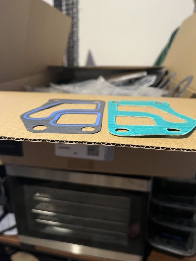
Next up is oil cooler gaskets, it seems like others have had issues with them leaking. I found 'Russ Repair' has some thicker gaskets for the oil cooler that come with Ford O-rings as well. I purchased them to compare to the CDD gaskets. The Russ gaskets (Green) measured .033 and the CDD (Grey) .016. I would imagine the thicker gasket would be less susceptible to splitting or crushing.

That about does it for seals and gaskets.
 

Attachments

  • IMG_9120.jpeg
    IMG_9120.jpeg
    213.9 KB · Views: 2
Last edited:

8769bigred

Registered User
Joined
Nov 5, 2024
Posts
53
Reaction score
31
Location
Portland Oregon
Next are the 'Hard Parts'

My exhaust valves were pitted pretty bad, and the head was already going to a shop, so I got new 'Turbo' rated valves.

Ford Part number F3TZ-6505-B or International 1816638C2. These were really affordable NOS on ebay.

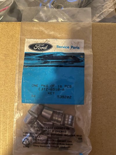
I also got new keepers, one of mine had a crack so I decided to replace the whole set - Ford E3TZ-6518-A

My oil cooler was plugged so I got a new one from CDD - looks incredible.

I went with the 'Gator' Head studs from CDD which sounds like a newer product for the 6.9 IDI. They have a higher torque rating than the older ARP sets that were/are available for the truck

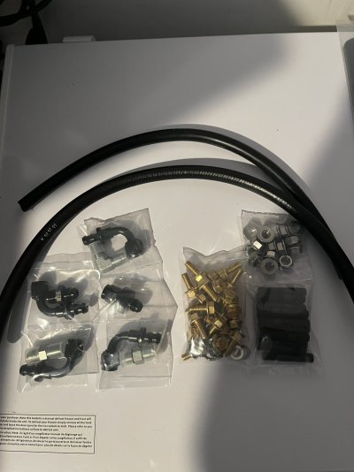
I also got some hard line deletes, oil pan bolts, and exhaust manifold studs from CDD. Pretty nice looking stuff.
 

Attachments

  • IMG_9124.jpeg
    IMG_9124.jpeg
    289.4 KB · Views: 3
  • IMG_9126.jpeg
    IMG_9126.jpeg
    236.5 KB · Views: 3
  • IMG_9125.jpeg
    IMG_9125.jpeg
    223.8 KB · Views: 3
  • IMG_9127.jpeg
    IMG_9127.jpeg
    228.9 KB · Views: 3

8769bigred

Registered User
Joined
Nov 5, 2024
Posts
53
Reaction score
31
Location
Portland Oregon
The next part to talk about is freeze plugs.

I purchased the CDD kit. I knew I would be removing the ones in the head but was not sure about the block.

I then learned the 7 large plugs in the block are special and need a tool to install. This tool basically needs to be custom made by a machine shop if you want to do that.

There is another procedure as well to drill out the block with a whole saw to allow 'standard' style freeze plugs to be installed. Justin at R and D idi Performance has a video on YouTube about this procedure.

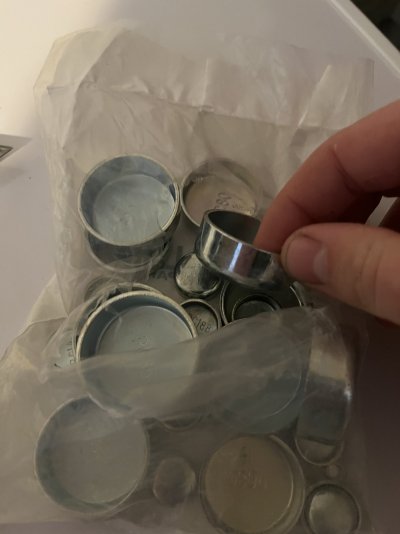
The plugs in the CDD kit do not match the factory plugs. I'm not sure if they are special and can be installed without issues or if they require the whole saw mod. The listing did say to use the OEM install tool, but I'm not sure how the OEM install tool would work with these plugs.

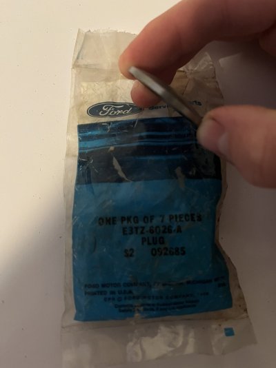
Here is a ford plug, part number E3TZ-6062-A

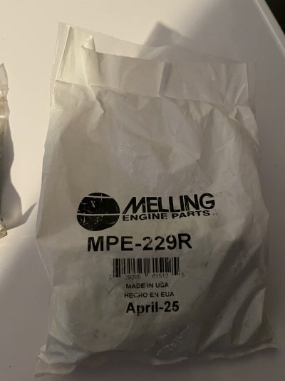
The Melling kit is from CDD

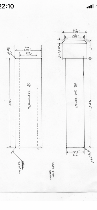
I found the schematic to make the ford tool. it was on some obscure website I can't remember the name of it.

Here is a link to a good write up on how to use the OEM ford tool and Plugs if you choose to. https://www.ford-trucks.com/forums/...um=button&utm_campaign=share&utm_content=post

With all this in consideration I think I'm going to leave my freeze plugs alone
 

Attachments

  • IMG_9123.jpeg
    IMG_9123.jpeg
    167.2 KB · Views: 6
  • IMG_9122.jpeg
    IMG_9122.jpeg
    175.2 KB · Views: 5
  • IMG_9121.jpeg
    IMG_9121.jpeg
    167.1 KB · Views: 6
  • IMG_9128.png
    IMG_9128.png
    954.8 KB · Views: 4

8769bigred

Registered User
Joined
Nov 5, 2024
Posts
53
Reaction score
31
Location
Portland Oregon
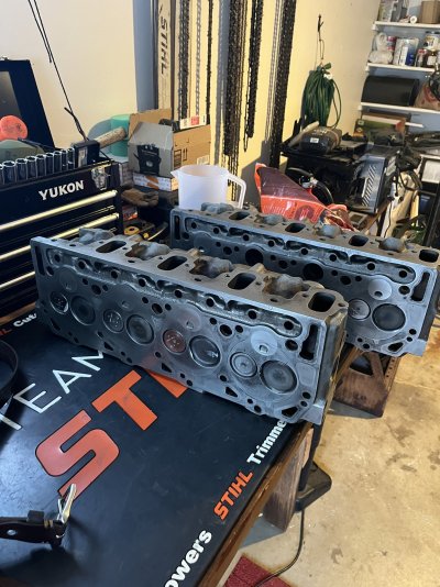
Small update but I got my heads back from the machine shop so that is cool. Hopefully I will have some time to assemble soon. My focus this weekend will be cab mounts and rivet replacement.
 

Attachments

  • IMG_9187.jpeg
    IMG_9187.jpeg
    386.9 KB · Views: 3

Olds64

Full Access Member
Joined
Nov 13, 2022
Posts
133
Reaction score
60
Location
Edmond, OK
There is another procedure as well to drill out the block with a whole saw to allow 'standard' style freeze plugs to be installed. Justin at R and D idi Performance has a video on YouTube about this procedure.

The plugs in the CDD kit do not match the factory plugs. I'm not sure if they are special and can be installed without issues or if they require the whole saw mod. The listing did say to use the OEM install tool, but I'm not sure how the OEM install tool would work with these plugs.


Having difficulty posting with my phone... anyways. :frustrate


Here's a thread that came up recently on FTE.


If Justin did a video on modifying the block to use standard freeze plugs I'd probably go that way. If the ones you got from CDD only work with the OE tool you could always call them and see if they'll let you exchange them.
 
Last edited:

8769bigred

Registered User
Joined
Nov 5, 2024
Posts
53
Reaction score
31
Location
Portland Oregon
@Olds64 The FTE write up you shared is very good. I have it linked above.

I found a machine shop locally that is making me the tool for $155. I considered the ‘drill’ method but with the small risk of damaging the block I decided for me it was worth it to just do it the factory way with the factory parts. Welch plugs and cup type plugs have been around for a long time I’m not sure why they chose to use the Welch style plug on the block.

As for the CDD kit, their plugs are all cup type so no special tools required like the website listings says. Although to utilize the cup plugs you would need to drill the block.
 

8769bigred

Registered User
Joined
Nov 5, 2024
Posts
53
Reaction score
31
Location
Portland Oregon
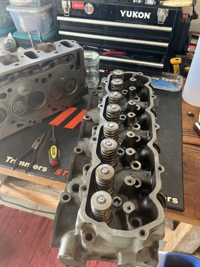
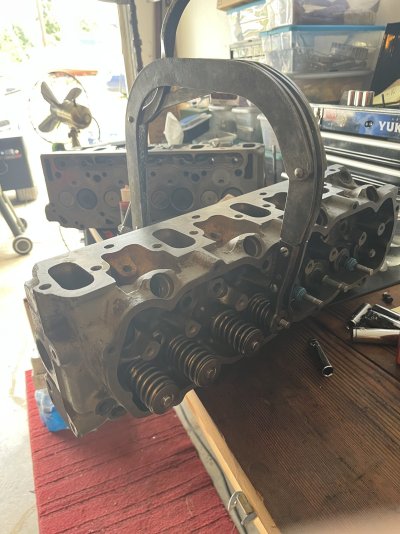
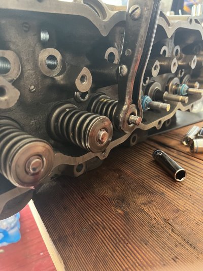
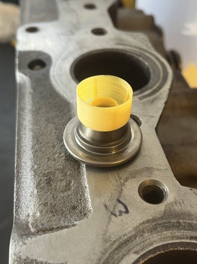
Made some progress today!! I got one cylinder head assembled today. I opted to use the ford OEM ‘umbrella’ seals on the exhaust valves. I used then PPR seals on the intake.

A bit of back story on the valve stem seals from all the reading I have done.


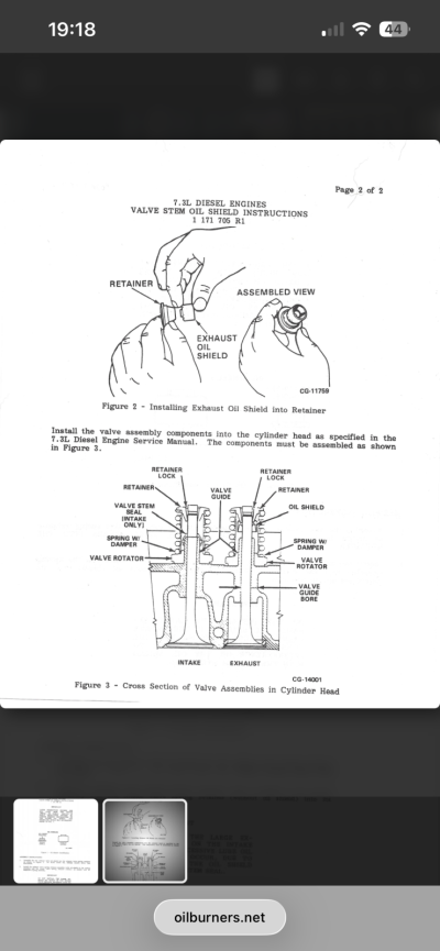
the 6.9 had the modern style seals on the intake from the jump in 1983 along with some small plastic ‘hats’ on the valve retainer. The exhaust valves used a loose fitting rubber seal from the looks of what I removed from my truck. Apparently ford tried using a ‘PPR’ style seal on the exhaust stems just like the intake. This was done on the 7.3 idi but resulted in premature valve guide wear. They then switched back to an umbrella type seal on the exhaust. This allowed oil to get to the valve guide without letting too much leak past I guess. Some people say to run the PPR seals on the valves, some say this leads to accelerated wear. The solution seems to be to use bronze guides with the PPR seals. My guides were in spec and the original cast iron so I decided to run the OEM sealing system.


here is a snippet from the 1993 Ford FSM about installing the seals and what goes where. This is almost the last year of the IDI so I see this information as the ‘final’ iteration of the valve train after a decade of production,
 

Attachments

  • IMG_9237.jpeg
    IMG_9237.jpeg
    363.6 KB · Views: 1
  • IMG_9234.jpeg
    IMG_9234.jpeg
    304.6 KB · Views: 1
  • IMG_9235.jpeg
    IMG_9235.jpeg
    367.5 KB · Views: 1
  • IMG_9236.jpeg
    IMG_9236.jpeg
    286.5 KB · Views: 1
  • IMG_9159.png
    IMG_9159.png
    341.8 KB · Views: 1
  • IMG_9158.png
    IMG_9158.png
    315.5 KB · Views: 1
Top