Manual Glow Plug update

bbjordan

Snow Monkey
Joined
Feb 24, 2011
Posts
1,421
Reaction score
393
Location
Ashern Manitoba
Having a few 6.9 IDIs, I am all too familiar with the glow plug controller failing resulting in 8 dead glow plugs. :mad:
So, as many other have done, I converted to a manual glow plug system. It has worked wonderfully. :)

No big news there, but not that long ago I was reading a thread on Using Glow Plugs to Super tune the engine:

http://www.ford-trucks.com/forums/593483-using-glow-plugs-to-super-tune-the-engine.html

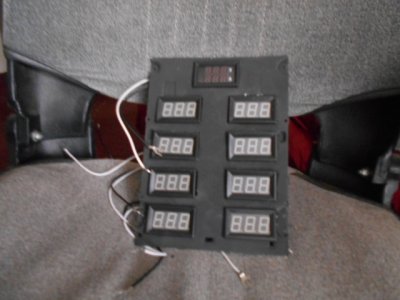
This really intrigued me. I like the idea of being able to see what each individual cylinder is doing, but I didn't like the idea of having to mess about with disconnecting and connecting glow plug wires all the time.

Someone on that thread suggested using standard Bosch style relays to allow you to still be able to glow the plugs, but when they are not being glowed be used to monitor cylinder temp.

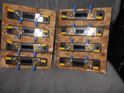
Well, recently 30 Amp relays and bases went on sale at Princess Auto for $4.99 a piece. I grabbed 8.
So I updated my glow plug system.

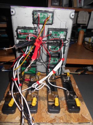
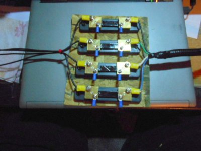
Here are the relays installed on the firewall:

You must be registered for see images attach


Close-up

You must be registered for see images attach


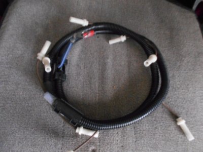
I stripped out the old glow plug controller wiring while I was at it because I do not intend to go back to the "automatic" system. The white wire going across the top is a CAT 5 solid strand copper wire that goes to the inside of the cab.

You must be registered for see images attach


You must be registered for see images attach


You must be registered for see images attach


As you can see, I have converted to the carrier fuel pump. This is an awesome upgrade. I used to have problems with cold starts. Well, not really problems, but it would take some cranking before it started. Warm starts were never a problem, they were almost instant. Now my cold starts are almost the same as my warm starts: almost instant. I highly recommend this upgrade.
 

argve

Resident Fruitcake
Joined
Dec 11, 2004
Posts
7,510
Reaction score
32
Location
Gwynneville, Indiana
that's a neat idea, I like it. you can get real time feedback on the running condition of the engine.
 

laserjock

Almost there...
Supporting Member
Joined
Nov 20, 2012
Posts
8,841
Reaction score
3,130
Location
Maryland
We actually had a thread on that over here a while back too. I suggested if you wanted to you could do exactly what you did with the 8 relays. The context was how do you test your GP's individually to find out which one it is that is bad without unhooking all of them and checking with a test light. It's a neat idea. I look forward to reading more about your findings. Are you going to data log the cylinder temps via reading gp resistance or just check it manually?
 

IDIoit

MachinistFabricator
Supporting Member
Joined
Aug 26, 2014
Posts
13,324
Reaction score
3,897
Location
commiefornia
that thread on FTE is fricken long!!!!

hlad i have a 3 day hospital stay ahead of me!!!
 

OLDBULL8

Good Morning Ya'll.
Supporting Member
Joined
Feb 12, 2009
Posts
9,923
Reaction score
338
Location
Delphos , Ohio
How about something like this? The volt meter will be hooked to an 8 position rotary switch to read the milli volts generated from each GP. The current meters will monitor each individual GP during the glow cycle. The cost for all this is probably prohibitive for an individual just to try and tune and monitor the GP's, besides all the meters in cab, where the hell ya gonna put them for every day use. I've got about $250 in parts now.
 

Attachments

  • DSCN0488.JPG
    DSCN0488.JPG
    130.1 KB · Views: 19
  • DSCN0492.JPG
    DSCN0492.JPG
    141.5 KB · Views: 16
  • DSCN0490.JPG
    DSCN0490.JPG
    129.5 KB · Views: 14
  • DSCN0491.JPG
    DSCN0491.JPG
    131.3 KB · Views: 14
  • DSCN0493.JPG
    DSCN0493.JPG
    80.1 KB · Views: 15

OLDBULL8

Good Morning Ya'll.
Supporting Member
Joined
Feb 12, 2009
Posts
9,923
Reaction score
338
Location
Delphos , Ohio
To add to the above post. You would have to have a video camera to catch the GP cycle readings, only got a few seconds to do that.
 

bbjordan

Snow Monkey
Joined
Feb 24, 2011
Posts
1,421
Reaction score
393
Location
Ashern Manitoba
We actually had a thread on that over here a while back too. I suggested if you wanted to you could do exactly what you did with the 8 relays. The context was how do you test your GP's individually to find out which one it is that is bad without unhooking all of them and checking with a test light. It's a neat idea. I look forward to reading more about your findings. Are you going to data log the cylinder temps via reading gp resistance or just check it manually?

I thought I had seen it suggested before, but I couldn´t remember where or when. When I read the Super Tuning thread, it was mentioned there. I agree it´s a neat idea. To test the glow plugs individually, I think an LED in parallel with the GP would work. If the GP is burnt out, the LED won´t light.

I looked at data loggers, but that stuff isn´t cheap. I´ll be happy just to get some millivolt meters.
 

bbjordan

Snow Monkey
Joined
Feb 24, 2011
Posts
1,421
Reaction score
393
Location
Ashern Manitoba
How about something like this? The volt meter will be hooked to an 8 position rotary switch to read the milli volts generated from each GP. The current meters will monitor each individual GP during the glow cycle. The cost for all this is probably prohibitive for an individual just to try and tune and monitor the GP's, besides all the meters in cab, where the hell ya gonna put them for every day use. I've got about $250 in parts now.

Ya! The first pic is like what I´m thinking about. I was thinking of 1 millivolt meter per plug. Do you have yours already mounted in your truck?
 

laserjock

Almost there...
Supporting Member
Joined
Nov 20, 2012
Posts
8,841
Reaction score
3,130
Location
Maryland
I may not be understanding what you are doing but a millivolt meter won't tell you much. You are looking for a small change in resistance of the GP due to cylinder temp. Need a resistance measurement. Might be able to do a 4 probe measurement but that requires current flowing through the plug which would heat it so not sure how that is helpful.

I second the cut and paste. I'd be interested in reading that.
 

bbjordan

Snow Monkey
Joined
Feb 24, 2011
Posts
1,421
Reaction score
393
Location
Ashern Manitoba
Here you go. It is a text file.

You must be registered for see images attach
 

Attachments

  • IDI Diesel Super Tuning extracts.txt
    102.4 KB · Views: 25

laserjock

Almost there...
Supporting Member
Joined
Nov 20, 2012
Posts
8,841
Reaction score
3,130
Location
Maryland
Just to clarify what OLDBULL is showing up there (he can correct me if I'm wrong) He has got panel ammeters and the required (large) current shunts to go with them. That's what the big metal strips are. Measuring the cylinder temperature I believe would require a resistance measurement.
 

laserjock

Almost there...
Supporting Member
Joined
Nov 20, 2012
Posts
8,841
Reaction score
3,130
Location
Maryland
Okay, I'll bite. I read through a lot of that document and while I in principle agree with most of what he is claiming he can tell, I don't seen anywhere it is mentioned how you get a voltage measurement off an un-energized glow plug. Resistance I understand. Voltage someone will have to help me with unless what they are measuring is leakage from somewhere but the GP relay is mechanical so I doubt it's coming from there. The controller is solid state and would have some leakage I would guess but not the relay.
 

bbjordan

Snow Monkey
Joined
Feb 24, 2011
Posts
1,421
Reaction score
393
Location
Ashern Manitoba
laserjock, you are using the thermocouple effect to get the millivolt reading. The glow plugs will actually produce a very small voltage when heated. The hotter, the greater the voltage. I don´t know if you can calibrate them, but at least you can see the difference cylinder to cylinder, and hotter vs colder. By bypassing the GP controller and relay entirely, we only measure the voltage when the glow plugs are not activated. The glow plug is connected to pin 30 on the Bosch relay. Normally this is circuit is closed to pin 87a where the millivolt gauge is connected. Only when the relay/plug is activated does it get current from pin 87, which is connected to the battery.

For reference:
You must be registered for see images attach


I think OLDBULL8 was looking to measure the current when the glow plug was activated.

In the Super Tuning thread, guys are manually unplugging the GPs and taking measurements, burning fingers etc...
 

Forum statistics

Threads
91,306
Posts
1,130,031
Members
24,117
Latest member
olsen726

Members online

Top