IP solenoid wiring question

argve

Resident Fruitcake
Joined
Dec 11, 2004
Posts
7,510
Reaction score
32
Location
Gwynneville, Indiana
Here is a wiring diagram I also included a manual control of the fast idle if you wanted to do that.
 

Attachments

  • Stock Wiring with Manual.JPG
    Stock Wiring with Manual.JPG
    49.7 KB · Views: 22
  • Stock wiring.JPG
    Stock wiring.JPG
    38.7 KB · Views: 13

OkieGringo

OkieGringo aka Baja
Joined
Dec 26, 2005
Posts
395
Reaction score
0
Location
Claremore, Oklahoma
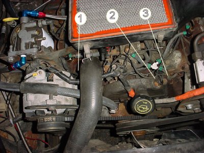
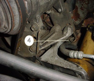
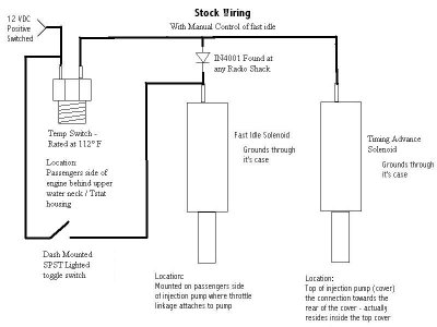
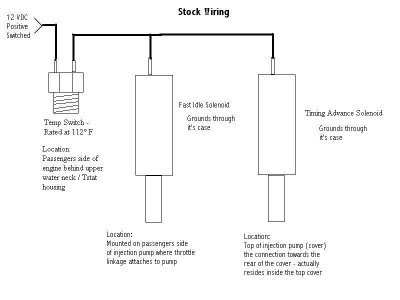
To check the connections to the IP, here's what you need to do. Turn on key to 'run' position. Check the main wire that comes from the loom to the IP (injection pump), does it have juice. The wire runs to the FSS (fuel shutoff switch) connector first, then to one side of the Cold Engine Switch(two-prong sensor, located in hole behind the upper radiator hose connection). When the engine is cold 'juice' will pass thru the sensor, if the sensor is good, and go to either the FIS (fast idle solenoid) or the CTA (cold timing advance), then to the other. If the engine is cold and sensor is good it will be 'closed' and allow 'juice' to get to the FIS plunger which holds the idle speed up. If FIS plunger is working, but not pushing up far enough, use a 1/4" wrench to turn/extend it until the idle speed is ~850 rpm. The CTA (cold timing advance) near the spider/distribution end of the IP 'advances the timing' to make engine run smoother/run cleaner/less smoke. The Cold Engine Switch opens/shuts off the electricity to the FIS and CTA after engine reaches 112 degrees, and engine speed/rpm will/should drop to ~650 rpm. If these three items are working correctly, when you go to start engine, hold the throttle pedal at least 1/2 way to floor to allow the FIS plunger to 'set' itself. Use a test light to check for electricity/juice at each of the solenoids, FSS, FIS and CTA. Let me know if this helps. Good luck, OkieGringo
 

krawlr

Yup, that's me
Joined
Jan 25, 2006
Posts
323
Reaction score
0
Location
Cincinnati, OH
Well I went and took some pix for what it's worth. My info is letting me down here. 1-is the switch for the cold running stuff. 2-is engine speed sensor 3-is a coolant sensor with a red/white wire 4-is a coolant sensor with a white wire.

It appears one of the sensors 3&4 is a switch for engine overtemp and they both tie into the same wire.

Again my info is unclear in this area. Doing the best I can with what I have.

And yes, if we have an ugliest engine contest, I have an unfair advantage. :backoff :draw

Edit: oops, forgot to hit the upload button.
 

Attachments

  • hauler 035.jpg
    hauler 035.jpg
    103.4 KB · Views: 15
  • hauler 036.jpg
    hauler 036.jpg
    60.2 KB · Views: 2

h2odrx

Anti-O
Joined
Dec 11, 2005
Posts
4,835
Reaction score
3
Location
Coastal Neckville, NC
argve said:
Here is a wiring diagram I also included a manual control of the fast idle if you wanted to do that.


The temp switch is a 2 wire located on the passenger front top of the engine,
ford wants $52 for that? your photo shows a 112f switch, if i go to a parts store i need to ask for one that is closed until 112f? someone had told me which way but i can't remember? mine shorted and melted alot of wires! so now i'll try to put them all back right! but i don't want to pay $52!!!!! :backoff
 

argve

Resident Fruitcake
Joined
Dec 11, 2004
Posts
7,510
Reaction score
32
Location
Gwynneville, Indiana
h2odrx said:
The temp switch is a 2 wire located on the passenger front top of the engine,
ford wants $52 for that? your photo shows a 112f switch, if i go to a parts store i need to ask for one that is closed until 112f? someone had told me which way but i can't remember? mine shorted and melted alot of wires! so now i'll try to put them all back right! but i don't want to pay $52!!!!! :backoff

It starts off closed then opens up once 112° is reached. You could do it with one that closes at 112° but we would need to install a relay and more wiring...
 

argve

Resident Fruitcake
Joined
Dec 11, 2004
Posts
7,510
Reaction score
32
Location
Gwynneville, Indiana
h2odrx said:
ok closed until 112 then open. and it is just a coolant temp switch?
thanks

yeppers - you got it. It runs / controls nothing else other than what I listed - heck truth be told I rode around with mine disconnected for quite sometime on The Enterprise because it never really effected me much...
 

jrisingmoon

Full Access Member
Joined
Dec 20, 2005
Posts
224
Reaction score
0
Location
Pensacola
Krawlr:
I see what the problem was: I don't have an engine speed sensor, the #2 in your picture, on my 6.9. I have 1, 3 and 4 but no 2. The two connectors that I said were behind the alternator, are closer to the water pipe than the alternator.

Argve:
I was thinking about putting a manual switch for the FSS in but I was having a hard time figuring out how to do it and if it was worth the work. I guess if the switch blows you could still get power to the FSS without having to replace it. The temp switch in your diagram is wired from left to right, facing the front of the engine, correct? I think I'll put the switch in just to be safe...

OkieGringo:
thanks for the post. that saved me from asking a question or two more.

Time to get the thing back together...
 

argve

Resident Fruitcake
Joined
Dec 11, 2004
Posts
7,510
Reaction score
32
Location
Gwynneville, Indiana
jrisingmoon said:
Argve:
I was thinking about putting a manual switch for the FSS in but I was having a hard time figuring out how to do it and if it was worth the work. I guess if the switch blows you could still get power to the FSS without having to replace it. The temp switch in your diagram is wired from left to right, facing the front of the engine, correct? I think I'll put the switch in just to be safe...

Easiest way to tell which way is which on the switch wiring... Just need to shut the truck off then turn the key back to the ON position (but the truck is not NOT running) - yank plug off temp switch - check the voltage on socket... which ever side has +12V is the side you want to land the manual switch to... With the system I laid out in the diagrams above the system will still work just like the factory engineer wanted it to but it gives you the ability to force the engine into a high idle condition but not advance the timing.

Now for those of you following this thread and don't understand why you would want to do such a thing here is one reason why... so that let's you wanted to let the truck run for an extended period of time (run into store but it's either hot or cold out and you want a comfy truck to return to) then just flip the switch, lock the doors and walk away knowing that she will not "wet-stack" or "wash down" so quickly whilst you are away.

I probably wouldn't recommend you leave it running for say like 2+ hours but that is your call...
 

Forum statistics

Threads
91,284
Posts
1,129,802
Members
24,101
Latest member
dieselmainiac

Members online

Top