Alaska red crewcab build thread

nelstomlinson

Full Access Member
Joined
Oct 21, 2015
Posts
1,112
Reaction score
717
Location
Delta Junction AK
I got the new ring filed to about a 0.020 gap like the others, and started installing pistons. Four in so far, and no more damaged rings yet.
I have the arrow on top of the piston pointing at the cam, and the large radius side of each con rod up against the outside of the journal, rather than the center.
You must be registered for see images attach

The engine has been sitting in the shop, in a plastic bag, for months now, so I'm wiping the dust out of the cylinders with WD40 on a rag. I have put a drop of assembly lube in each ring groove, and smeared a drop on the piston skirts, and put a drop on the big end bearings.

I'm planning to take next week off, so maybe I can make some real progress on this.

Edited to add: Got all eight pistons in, no more damaged rings. I haven't torqued the main and rod bolts yet. Now I need to figure out how to degree the cam.
 
Last edited:

nelstomlinson

Full Access Member
Joined
Oct 21, 2015
Posts
1,112
Reaction score
717
Location
Delta Junction AK
Today I finally made time to degree the cam. I'm wondering how much lift above the base circle I can tolerate at TDC? It looks as if I have somewhere between 0.020" to 0.030" inches of cam lift at TDC, for intake and exhaust. It's definitely off the base circle there.

Russ tells me to just line up the timing marks on the gears and I'm good to go, and that's what I did. Here is what that looks like for a typ4 cam:
You must be registered for see images attach

The exhaust opens pretty wide, the intake not much wider than stock. Here is the data as I wrote it down:
You must be registered for see images attach

Take those numbers with a shaker of salt: the degree numbers are probably +/-5 degrees, and the cam lift numbers are certainly +/-4 thousandths or a little worse.
 

david85

Full Access Member
Joined
Feb 21, 2008
Posts
4,820
Reaction score
1,083
Location
Campbell River, B.C.
Today I finally made time to degree the cam. I'm wondering how much lift above the base circle I can tolerate at TDC? It looks as if I have somewhere between 0.020" to 0.030" inches of cam lift at TDC, for intake and exhaust. It's definitely off the base circle there.

Russ tells me to just line up the timing marks on the gears and I'm good to go, and that's what I did. Here is what that looks like for a typ4 cam:
You must be registered for see images attach

The exhaust opens pretty wide, the intake not much wider than stock. Here is the data as I wrote it down:
You must be registered for see images attach

Take those numbers with a shaker of salt: the degree numbers are probably +/-5 degrees, and the cam lift numbers are certainly +/-4 thousandths or a little worse.
Very cool, thanks for sharing this. Do you have a chart for the stock cam so we can get a visual comparison?
 

nelstomlinson

Full Access Member
Joined
Oct 21, 2015
Posts
1,112
Reaction score
717
Location
Delta Junction AK
Very cool, thanks for sharing this. Do you have a chart for the stock cam so we can get a visual comparison?
I do not have anything for the stock cam. As I said, take my numbers with a grain of salt. The dial indicator wasn't mounted quite as firmly as I wanted, and I wasn't even trying to be precise with the degrees.

I believe I've read here that the stock cam has about a 0.258 lift on both intake and exhaust lobes? So this is opening the exhaust a lot farther, pretty close to stock for the intake. Looking at the lower left and lower right corners, there isn't much overlap, and given how close the piston is to the valves at TDC, there really couldn't be.
 

nelstomlinson

Full Access Member
Joined
Oct 21, 2015
Posts
1,112
Reaction score
717
Location
Delta Junction AK
Finally getting back onto this project. I found a complete Sidewinder in my shop, and assembled it on an old engine on a stand in the shop, and got inspired.
You must be registered for see images attach
 

nelstomlinson

Full Access Member
Joined
Oct 21, 2015
Posts
1,112
Reaction score
717
Location
Delta Junction AK
I noticed that the lifters have an oil hole on one side, and figured that side needs to go toward the oil gallery. I bolted the oil pump on the bottom, no gasket between the pump and block.

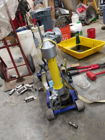
I assembled the oil cooler. I put both o rings on one end, lubed them with a smear of dielectric grease, put a board across it and sat on it. The one end eventually popped in. The second end didn't want to go together, so I strapped it to the floor jack, pumped it until the strap was tight, then smacked it on the top with the dead blow, and it snapped together.
 

Attachments

  • AssemblingOilCooler.jpg
    AssemblingOilCooler.jpg
    366.6 KB · Views: 11

Old Goat

Full Access Member
Joined
Jan 14, 2021
Posts
1,645
Reaction score
1,633
Location
Northern Nevada
I just read through your thread. Don`t know how I missed it before.
Interesting you painted your OC Yellow.
When I did mine a few years back, I painted mine yellow also. Mainly so I could see if there is any leaks looking down on it with the Hood open.
It is John Deere yellow.

You really have your plate full with all your projects.
If this endless winter here would end, I can get to mine. I have too many irons in the fire.


Goat
 

nelstomlinson

Full Access Member
Joined
Oct 21, 2015
Posts
1,112
Reaction score
717
Location
Delta Junction AK
I got the gear train on the front lined up.
You must be registered for see images attach


I am putting in a Motorcraft t-stat. The International manual says the genuine thermostat will have no washer at the bottom, and will have a rubber sleeve. This looks legit.
You must be registered for see images attach


Finally, the gasket kit includes a thick bit of soft rubber, like a very short cylinder. I have no idea what that's for. Anyone have a clue?
You must be registered for see images attach
 

IDIBRONCO

IDIBRONCO
Joined
Feb 5, 2010
Posts
12,312
Reaction score
11,021
Location
edmond, ks
That's a new seal for the back side of your CDR. It goes between the CDR and intake.
 

nelstomlinson

Full Access Member
Joined
Oct 21, 2015
Posts
1,112
Reaction score
717
Location
Delta Junction AK
Got the front cover on, got the waterpump and injector pump gear housing on, got the engine painted.
You must be registered for see images attach

Somehow I hadn't saved the waterpump and front cover bolts. I had to trim some Grade 8 bolts to the right length. Fortunately I keep a little stash of hardware in the shop, to prevent trips to the hardware store, so I had some 5/16NC on hand to work with.
 

Cant Write

Full Access Member
Joined
Sep 29, 2021
Posts
866
Reaction score
720
Location
Placerville CO
Are you still planning a trip to Prudhoe Bay when you finish this pickup up?

Did you do anymore to your “trash” trailer? I love that thing!! (Mount the toolbox or 100 gal fuel tank)
 
Top