Okay, let me see what I can do. Based on your pictures, I'm going to assume that your truck is an '83-'86. If it's an '87-'94, the wiring is different...if this is the case, disregard my post.
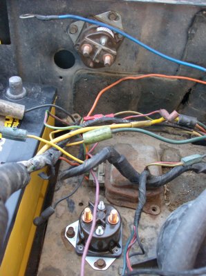
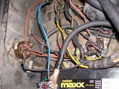
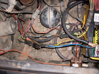
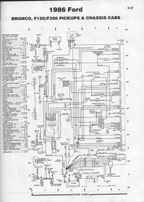
The wiring diagram makes it look like there should be two relays, one for the starter and one for the glow plug system. Is this correct? The relay on the fender is what was in there when I bought the truck, I just added the one next to the voltage regulator.
This is correct. The relay on the fender is the starter relay; the one next to the voltage regulator is the glow plug relay.
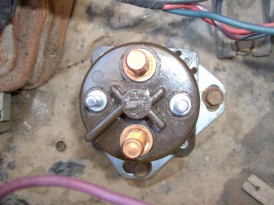
What post do I connect to the battery, to ground, to the glow plug controller (purple wire) and where the heck do the other wires go?
The wire from the battery should go onto one of the big terminals; the wires going to the glow plugs should go to the other big terminal. In this case, it doesn't matter which of the two large terminals you use, as long as the wires going to the plugs is on the terminal opposite the wire going to the battery.
")
Regarding the ground and the glow plug controller wires, my memory's a bit fuzzy. IIRC, the relay also grounds to the metal tabs on the bottom. So, you should be able to do a continuity check between the metal mounting tabs and one, then the other small terminal. Connect the ground wire to the small terminal that has continuity with the mounting tab, and connect the controller wire to the other small terminal.
I'm about 85% sure on this...if I'm wrong, someone please correct me!! Unfortunately, I don't have my old GP relay handy to test. You can test the relay function, however. The '83-'86 glow plug system doesn't sense current running to the plugs, so the relay and controller will function the same way with the plugs wired in as with them disconnected. To test it, connect every wire to the GP relay as I described, except for the wires going to the glow plugs themselves. There should be a wire going to the glow plug light in the cab (IIRC, it's dark green); connect this to the large terminal opposite the wire going to the battery (the same terminal that the wires to the plugs themselves will go onto). Then, turn the key ON. If the light cycles normally (on for 8 seconds, off for 10 seconds or so, then back on), it's wired correctly...if the light stays on solidly, reverse the glow plug and ground wires and try again. If the light still stays on solid, the controller may be stuck.
Regarding the other wires, I'm not sure which wires you need info for and which you're okay with. I have a wiring diagram here (a factory shop manual for an '84); if you can give me the colors/striping patterns for the wires you need info on, I should be able to tell you what the wire's for (and therefore where it goes)
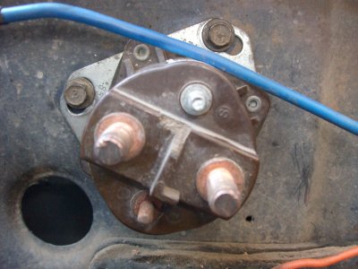
There is a wire that runs along the positive cable to/from the starter solenoid. Is that a ground or positive line?
If this is the wire I think you're talking about, it's the trigger wire for the starter. It would go on the large terminal on the fender-mounted starter solenoid opposite of the terminal that you connect to the battery.
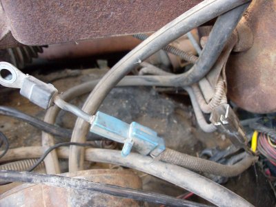
Does the little metal cylinder get attached to ground on the fender or not at all?
If you're talking about the condenser that's laying on the battery in the third picture, on my truck, it's grounded. One of the screws that holds the voltage regulator down, also goes through the eye that's wrapped around the condenser.
There is a black wire that looks to have a ground connector on the end, can I run that directly to the battery negative post?
Was this in one of your pictures? ...there are a number of ground eyes in this area, most of which are grounded to the fender. But, I don't see a reason not to hook them directly to the negative terminal, except for issues with lengthening the wire(s) and messiness on the battery.
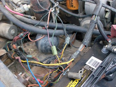
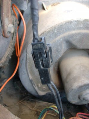
Also, on the drivers side under the brake master cyl, there are a couple of connections that don't seem to go anywhere, one with a blue connection and the other has two brown lines that come together in a brown female spade connector. Like I said, need a "little" help.
Could these wires be for the water separator? Another possibility is that they're meant to go into a relay that's mounted on the driver's side fender on some trucks, meant to supply power to the running light circuit on the trailer plug in the back. I'm not sure either way, though...
I hope this helps a little bit...good luck!!


![202817398bqlhiu_fs[1].jpg](/data/attachments/17/17113-1a388ca7ff73f3593ff7f01067ebb5a0.jpg)
![202817932OgmYDQ_fs[1].jpg](/data/attachments/17/17114-6468e1aea8e53f079f5a103b594ab909.jpg)
![202818090qsyRbK_fs[1].jpg](/data/attachments/17/17115-8f353ca7fcdeaf6a00a36933f0b301b6.jpg)