So I recently added another IDI to the family and one of the many problems it has is the glow plug caps have turned to dough. What's left of the metal underneath is corroded and not so conductive. The P.O said the glow plug controller didn't work. Just started clickin' right away. Huh. That's odd. Why would it malfunction...?
Parts list... I'm busy so a pic or two will have to suffice for the parts list.
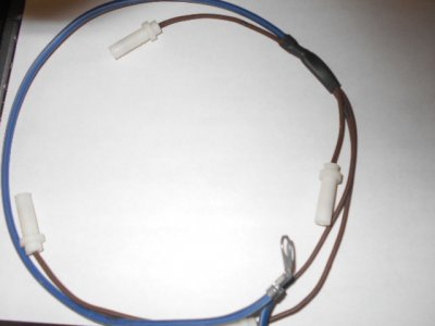
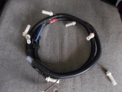
If you don't know the condition of the wire running your glow plug harness you should inspect it for pinches, exposed threads, corrosion, etc., and if necessary replace it. I had 10 gauge wire on hand, but 10 would not trip the glow plug timer properly because the controller works on resistance. I'm not getting into that here but you can research gp controllers and how they work if necessary. Pretty sure the stock harness gauge is 14. My trucks tend to start and stop a lot whether it is business related or running around with the kids so the manny glow plug switch was already happening immediately after this repair. I really like being in control of the gp system and it is an easy and cheap mod. I've done 2 now.
I got the snap connecters from Home Depot. They were $2.65/box? Roughly. I couldn't find the females only and you will not be using the males. The glow plug tip fits into the end meant for the male connector (the large end).
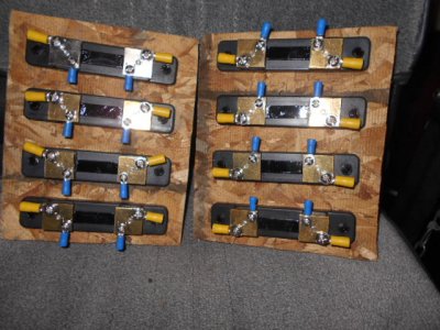
I crimped the first bank before deciding to solder everything together to make a better connection. Crimping is not going to hold up in this situation in my opinion. These connections are tight and getting them off while working underneath injector lines and turbo housings increases the likelihood of failure. I removed and rebuilt both banks with solder. If using solder I would recommend either pushing the plastic sleeve away from the wired end or trimming it so there is less plastic contamination.
I learned something at the end I should have done in the beginning... Before putting on the cap and soldering slide a 1/2" long piece of shrink tubing onto the wire that is the smaller diameter for the wire size. It will be probably 1/2" and will shrink to 1/4". It will make a better seal. If this note is confusing, you will understand in a minute. ANYWAY, next you will strip the wire about 1/2" and insert it into the snap cap.
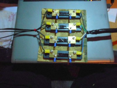
I used a needle nose here, but I also used a pliers to hold the cap while I soldered. It is a ***** to get everything to set just right. Be patient. It's worth it. I bent the wire on a 90 and melted solder on the exposed area then bent the wire on a 90 the other way to make a ring of solder all around the cap's "cup".
The mechanic at the shop had a metal parts box labeled "Shrinky Dinky Tube" for his shrink tube assortment Retired NYC police officer. You just can't teach someone that isn't from NYC to say MotherF@#$er the way a New Yorker does it. It's impressive. Anyway, I brought my own Shrinky **** Tube because I didn't want to be a Thievin' MotherF@#$er.
So here's where the little piece of 1/2" shrink tube comes in. You can't get it on over the cap so it needs to be on there already. Slide it over the shrink tube you just finished so that half is on the shrink tube and half is on the wire. Once you shrink it you will have a better seal on the wire and added strength where it overlaps. I didn't realize I had the smaller diameter tubing til my last two gp wires.
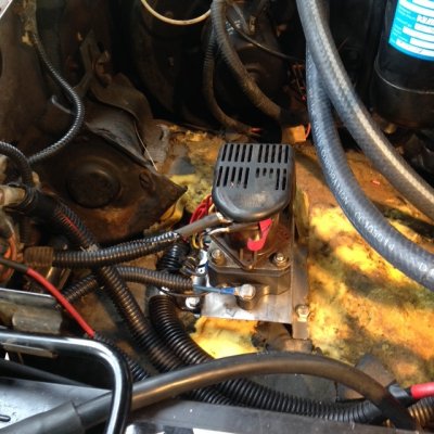
Hope this helps those with disintegrating gp caps. Total cost had I done new wiring as well would still have been less than $25. Took a few hours, but I wasn't in a hurry. The cool benefit I hadn't planned on is when you use these caps and the shrink tube they feel just like the originals.
You must be registered for see images attach
Parts list... I'm busy so a pic or two will have to suffice for the parts list.
You must be registered for see images attach
You must be registered for see images attach
If you don't know the condition of the wire running your glow plug harness you should inspect it for pinches, exposed threads, corrosion, etc., and if necessary replace it. I had 10 gauge wire on hand, but 10 would not trip the glow plug timer properly because the controller works on resistance. I'm not getting into that here but you can research gp controllers and how they work if necessary. Pretty sure the stock harness gauge is 14. My trucks tend to start and stop a lot whether it is business related or running around with the kids so the manny glow plug switch was already happening immediately after this repair. I really like being in control of the gp system and it is an easy and cheap mod. I've done 2 now.
I got the snap connecters from Home Depot. They were $2.65/box? Roughly. I couldn't find the females only and you will not be using the males. The glow plug tip fits into the end meant for the male connector (the large end).
You must be registered for see images attach
I crimped the first bank before deciding to solder everything together to make a better connection. Crimping is not going to hold up in this situation in my opinion. These connections are tight and getting them off while working underneath injector lines and turbo housings increases the likelihood of failure. I removed and rebuilt both banks with solder. If using solder I would recommend either pushing the plastic sleeve away from the wired end or trimming it so there is less plastic contamination.
You must be registered for see images attach
I learned something at the end I should have done in the beginning... Before putting on the cap and soldering slide a 1/2" long piece of shrink tubing onto the wire that is the smaller diameter for the wire size. It will be probably 1/2" and will shrink to 1/4". It will make a better seal. If this note is confusing, you will understand in a minute. ANYWAY, next you will strip the wire about 1/2" and insert it into the snap cap.
You must be registered for see images attach
I used a needle nose here, but I also used a pliers to hold the cap while I soldered. It is a ***** to get everything to set just right. Be patient. It's worth it. I bent the wire on a 90 and melted solder on the exposed area then bent the wire on a 90 the other way to make a ring of solder all around the cap's "cup".
You must be registered for see images attach
The mechanic at the shop had a metal parts box labeled "Shrinky Dinky Tube" for his shrink tube assortment
Retired NYC police officer. You just can't teach someone that isn't from NYC to say MotherF@#$er the way a New Yorker does it. It's impressive. Anyway, I brought my own Shrinky **** Tube because I didn't want to be a Thievin' MotherF@#$er.
You must be registered for see images attach
You must be registered for see images attach
So here's where the little piece of 1/2" shrink tube comes in. You can't get it on over the cap so it needs to be on there already. Slide it over the shrink tube you just finished so that half is on the shrink tube and half is on the wire. Once you shrink it you will have a better seal on the wire and added strength where it overlaps. I didn't realize I had the smaller diameter tubing til my last two gp wires.
You must be registered for see images attach
Hope this helps those with disintegrating gp caps. Total cost had I done new wiring as well would still have been less than $25. Took a few hours, but I wasn't in a hurry. The cool benefit I hadn't planned on is when you use these caps and the shrink tube they feel just like the originals.