DIY: Digital Pyrometer Gauge

BDCarrillo

Supporting Member
Supporting Member
Joined
Jul 19, 2014
Posts
1,245
Reaction score
10
Location
Abilene TX
You must be registered for see images attach

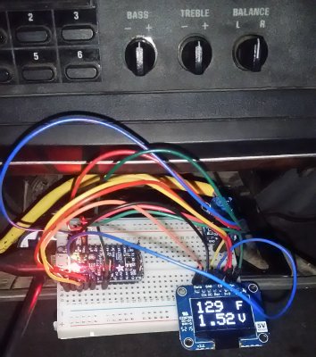
I didn't really like the Banks gauge... so, ta daaaa! It's about $40 in parts, with the screen being half of that. The enclosure is up to your imagination. You can change it from *F to *C in the code, and can see the actual voltage from the pyro-amp output. Obviously it'd be really compact without the breadboard. Truck was off for a bit, so it's reading residual heat after a test run prior to the photo.

Wiring is pretty simple... I'll work up a diagram in the future. Right now it's powered by USB in it's prototype form, but it can easily take a key-on 12v source.

Basic Parts:
Adafruit Pro Trinket (5v)
128x64 OLED

For Pyro Readout:
K Type Thermocouple Amp

For Boost Readout:
MPX 4250DP (36 PSI boost max measurement capability)


EDIT: Code updated to display average of 10 samples

Arduino Sketch:
Code:
[SIZE=1]

#include <SPI.h>
#include <Wire.h>
#include <Adafruit_GFX.h>
#include <Adafruit_SSD1306.h>
// If using software SPI (the default case):
#define OLED_MOSI   9
#define OLED_CLK   10
#define OLED_DC    11
#define OLED_CS    12
#define OLED_RESET 13
Adafruit_SSD1306 display(OLED_MOSI, OLED_CLK, OLED_DC, OLED_RESET, OLED_CS);
#define XPOS 0
#define YPOS 1
#define DELTAY 2
int convertTemp = 0;
float convertPSI = 0;
const int numReadingsPSI = 10;
int readingsPSI[numReadingsPSI];      // the readings from the analog input
int readIndexPSI = 0;              // the index of the current reading
int totalPSI = 0;                  // the running total
int averagePSI = 0;                // the average
const int numReadingsPYRO = 10;
int readingsPYRO[numReadingsPYRO];      // the readings from the analog input
int readIndexPYRO = 0;              // the index of the current reading
int totalPYRO = 0;                  // the running total
int averagePYRO = 0;                // the average
void setup() {
 display.begin(SSD1306_SWITCHCAPVCC);
 display.clearDisplay();
 display.setTextSize(3);
 display.setTextColor(WHITE);
 display.setTextSize(4);
  for (int thisReadingPSI = 0; thisReadingPSI < numReadingsPSI; thisReadingPSI++) {
    readingsPSI[thisReadingPSI] = 0;
  }
    for (int thisReadingPYRO = 0; thisReadingPYRO < numReadingsPYRO; thisReadingPYRO++) {
    readingsPYRO[thisReadingPYRO] = 0;
  }
}
void loop() {

//AVERAGE PSI
  // subtract the last reading:
  totalPSI = totalPSI - readingsPSI[readIndexPSI];
  // read from the sensor:
  readingsPSI[readIndexPSI] = analogRead(A0);
  // add the reading to the total:
  totalPSI = totalPSI + readingsPSI[readIndexPSI];
  // advance to the next position in the array:
  readIndexPSI = readIndexPSI + 1;
  // if we're at the end of the array...
  if (readIndexPSI >= numReadingsPSI) {
    // ...wrap around to the beginning:
    readIndexPSI = 0;
    averagePSI = totalPSI / numReadingsPSI;
  }
  //AVERAGE PYRO
  // subtract the last reading:
  totalPYRO = totalPYRO - readingsPYRO[readIndexPYRO];
  // read from the sensor:
  readingsPYRO[readIndexPYRO] = analogRead(A1);
  // add the reading to the total:
  totalPYRO = totalPYRO + readingsPYRO[readIndexPYRO];
  // advance to the next position in the array:
  readIndexPYRO = readIndexPYRO + 1;
  // if we're at the end of the array...
  if (readIndexPYRO >= numReadingsPYRO) {
    // ...wrap around to the beginning:
    readIndexPYRO = 0;
    averagePYRO = totalPYRO / numReadingsPYRO;
  }
//DISPLAY START
display.clearDisplay();

    convertTemp = (((averagePYRO*(5.0/1023.0)-1.25)/.005)*9/5+32);
    convertPSI = (((averagePSI*(5.0/1023)/.01845)-9)*0.14503773773020923);
  
    display.setCursor(12,0);
    display.println(convertTemp);
    if (convertPSI<9.999)
    {
    display.setCursor(36,34);
    }
    else
    {
    display.setCursor(12,34);
    }
    display.println(abs(convertPSI),1);
    display.display();

  }
[/SIZE]
 

Attachments

  • DSC_0004.JPG
    DSC_0004.JPG
    837.1 KB · Views: 140
Last edited:

laserjock

Almost there...
Supporting Member
Joined
Nov 20, 2012
Posts
8,841
Reaction score
3,130
Location
Maryland
Awesome. I've been considering consolidating gauges to a digital display. I've got an arduino and a display and a thermocouple amplifier to play with. Just haven't had time to screw with it. That's inspiring though.
 

mjs2011

Full Access Member
Joined
Jun 8, 2013
Posts
307
Reaction score
5
Location
Brookings, SD
Thats the same thermocouple amplifier that I use in my wvo controller that I've posted on here. Nice work. I know a lot of people mentioned to me that a visual is sometimes useful as well. Maybe instead of reporting voltage, you could have a bar graph from left to right that visually depicts EGT. Then you could code it to change color based on the temperature, or even flash of EGTs got over say 1200*F

Sent from my VS990 using Tapatalk
 

mjs2011

Full Access Member
Joined
Jun 8, 2013
Posts
307
Reaction score
5
Location
Brookings, SD
I just now realized it's an OLED, so no color changing, but the blinking and simple bar graph would still be possible. And it's nice and small so the install could be really clean.

Sent from my VS990 using Tapatalk
 

BDCarrillo

Supporting Member
Supporting Member
Joined
Jul 19, 2014
Posts
1,245
Reaction score
10
Location
Abilene TX
The voltage output was just for diagnostics. Eventually it'll display boost on the bottom, but I gotta find a good sensor for that and a spot on my 1G Banks kit to tie in. I was looking at the MPX4250AP MAP Sensor but the data sheet says 2.9-36.3 PSI for measurement range... presumably I'd have to subtract ambient barometric pressure to figure out the actual manifold pressure, which would put it in a good operating range for that sensor.

The OLEDs I'm using are monochrome, so no color flash. LEDs or a NeoPixel stick could easily act as a visual bar gauge and alarm.
 
Last edited:

FarmerFrank

Full Access Member
Joined
Sep 5, 2013
Posts
1,364
Reaction score
59
Location
Blairsville, Pa
I absolutely love the idea of this but I also know absolutely nothing about this caliber of electronics. I'll ask my oldest brother, he usually puts electronic stuff into engine terms for me so I can understand.


Sent from my iPhone using Tapatalk
 

riotwarrior

Supporting Member
Supporting Member
Joined
Sep 19, 2006
Posts
14,778
Reaction score
483
Location
Cawston BC. Canada
See...my guage pod would allow custom fitted stuff...not just round guages.....especially big sloped area above HVAC controls...that will be set up for sumptin!;Sweet :dunno
 

BDCarrillo

Supporting Member
Supporting Member
Joined
Jul 19, 2014
Posts
1,245
Reaction score
10
Location
Abilene TX
See...my guage pod would allow custom fitted stuff...not just round guages.....especially big sloped area above HVAC controls...that will be set up for sumptin!;Sweet :dunno

True true... but imagine shipping that big 'ol thing!

Update on the Pyro (&Boost gauge):
Changed the coding to avoid using "delay" (it's a clunky way of slowing down the screen updates from hundreds of times per second) and now it'll wait until there's a 10* change. That'll also allow me to run two parallel IF loops to update boost and pyro independently. I found a differential pressure sensor that oughta work. It's basically two sensors, one for ambient, one for boost. It's in the mail... I'll have to find a spot on the 1G Banks to tap into.
 
Last edited:

rotarydragon

Full Access Member
Joined
Apr 18, 2016
Posts
141
Reaction score
14
Location
Iowa
True true... but imagine shipping that big 'ol thing!

Update on the Pyro (&Boost gauge):
Changed the coding to avoid using "delay" (it's a clunky way of slowing down the screen updates from hundreds of times per second) and now it'll wait until there's a 10* change. That'll also allow me to run two parallel IF loops to update boost and pyro independently. I found a differential pressure sensor that oughta work. It's basically two sensors, one for ambient, one for boost. It's in the mail... I'll have to find a spot on the 1G Banks to tap into.

Gah, now I'v got to pull out my Arduino and start tinkering again! I keep kicking about the notion of removing that horrid disaster of a lighting system and changing it over to a micro controller controlled disaster of my own making.

I stopped programming for a reason ya know and now you've got me itching to do it again! :D Now lesse, did they ever update that .NET version of the Arduino...
 

BDCarrillo

Supporting Member
Supporting Member
Joined
Jul 19, 2014
Posts
1,245
Reaction score
10
Location
Abilene TX
Gah, now I'v got to pull out my Arduino and start tinkering again! I keep kicking about the notion of removing that horrid disaster of a lighting system and changing it over to a micro controller controlled disaster of my own making.

I stopped programming for a reason ya know and now you've got me itching to do it again! :D Now lesse, did they ever update that .NET version of the Arduino...

I doubt C has changed much over the years :) My other effort in progress is here: Arduino Timing Meter
 

rotarydragon

Full Access Member
Joined
Apr 18, 2016
Posts
141
Reaction score
14
Location
Iowa
I doubt C has changed much over the years :) My other effort in progress is here: Arduino Timing Meter

Nah, I'm sure pointers still make people want to scream :D Neat! I was also kicking about creating a fuel flow meter to determine fuel into the injection pump and fuel out to get an accurate read on what's in the tank plus how much fuel is really being consumed. All this because my fuel gauges are off of course. I mean, why just do the simple thing and replace the sending units or track down ground issues when you can grossly overcomplicate the problem and make cool toys?
 

needlenose

Full Access Member
Joined
Dec 9, 2013
Posts
399
Reaction score
87
Location
Irrelevant Data

BDCarrillo

Supporting Member
Supporting Member
Joined
Jul 19, 2014
Posts
1,245
Reaction score
10
Location
Abilene TX
I chose not to have it check every X milliseconds, although that would work. You'd still see minor fluctuations of a few degrees every X milliseconds, which is below a realistic detection threshold... it's just noise of a millivolt or two.


UPDATE
As the code sits now I'll get an updated readout after a 10* change, regardless of how fast it happens. I've posted the new code in the first post, with the PSI display stuff commented out.

UPDATE 2
Settled on the MPX4250DP, since it only outputs a difference between two inputs. One will be ambient, the other will be boost.

Got it all wired up into a compact package and fixed up the boost display code. Had to work around oled screen output placement and only outputting 1 digit past the decimal. The sensor I chose has a pretty broad range up to 36 psi of differential, so a realistic resolution is around +/-7.5 hundredths of a psi. I may need to implement a timer to limit screen updates since it's a touchy sensor. Still need to find a boost source and good tubing to run inside to the dash.

UPDATE 3
Little hose barb adapter and hose inbound for the boost portion. Test mule is down... banks air box being disposed of and turbo plumbing being reworked
 
Last edited:

laserjock

Almost there...
Supporting Member
Joined
Nov 20, 2012
Posts
8,841
Reaction score
3,130
Location
Maryland
Okay. I'm really glad that you pulled this up to the top. I started messing with my stuff today and I have the same thermocouple amp. My reading is running 2-5 degrees low at room temperature and in an ice bath. I keep seeing mention of a reference but I can't find any info on if it actually has anything to do with the temp reading. I tried it on two different thermocouples. Not sure how much it would matter in the grand scheme as long as it's a linear deviation.

Any thoughts? Did you calibrate yours at all?
 
Top