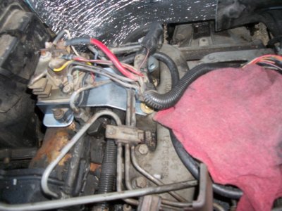
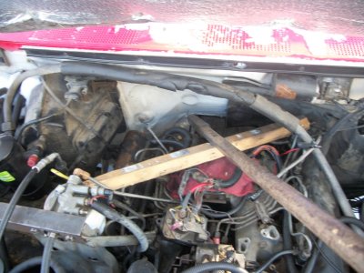
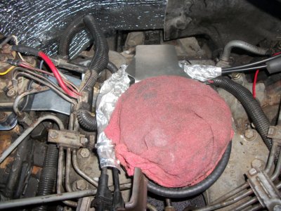
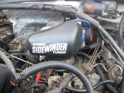
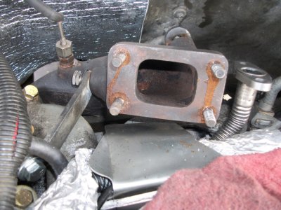
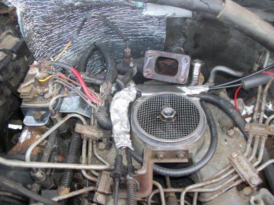
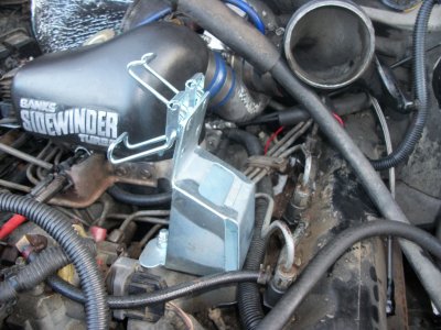
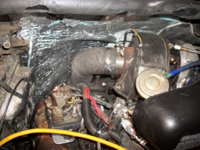
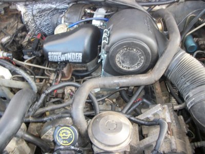
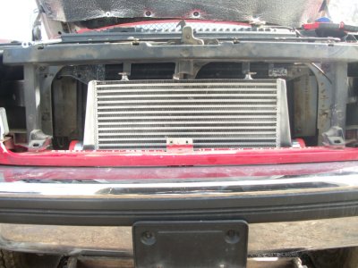
it's the moment you've all been waiting for tonight on log truck (well ok,maybe just me lol) as the banks turbocharger finds it's new home under the hood!............
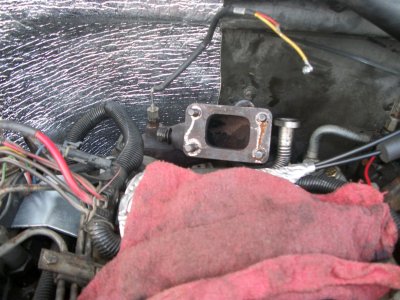
yeah,it's more of the hard stuff.fitting the turbo bolts on without dropping washers or nuts....fitting that monster dp (the wrap doesn't help) down into what seems to be an impossible fit.........and then the joy of bolting up the turbo drain with gasket.that's not exactly easy either.
be prepared for more choice words and bloody knuckles as you move forward with step 17.............
17.
Important! Alignment of the turbocharger and
intake components is determined by the tightening
of the two lower nuts where the inlet casting
bolts to the exhaust manifold. The following outlines
the alignment procedure.
A. Install exhaust gas temperature pyrometer probe in
the 1⁄4 NPT boss near the turbo mounting flange. Use
anti sieze compound on the probe threads. If a pyrometer
probe was not supplied, install a 1⁄4” NPT hex pipe
plug.
B. Install the 5 inch diameter o-ring on the intake manifold
inlet flange (make sure surface is free of oil, dirt,
old gasket, etc.).
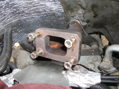
C. Temporarily set the turbocharger in place on the turbine
inlet casting and secure it with a couple of 3⁄8 – 24
stainless collet lock nuts, finger tight.
D. Set the pressure chamber casting in place on the
intake manifold. Make sure the pressure chamber
drops over the o-ring. Install the pressure chamber
with a 3⁄8 – 16 x 4” bolt, 3⁄8” AN washer, and 3⁄8” sealing
(o-ring) washer. Lightly snug the bolt so the pressure
chamber can be rotated slightly on the intake manifold.
E. Adjust the position of the turbocharger and pressure
chamber to provide the best side-to-side line up
of the turbo compressor hose joint while providing
clearance between the turbine heat shield and the firewall.
Additional firewall clearance may be obtained by
slightly bending the turbine heat shield at either side
of the slit in the shield. The turbine inlet casting can be
adjusted for position by tightening the two nuts at the
exhaust manifold studs. Start by alternately tightening
the nuts until they are evenly tight against the casting
flange. If the side-to-side alignment is off, the turbo
location may be adjusted by tightening one nut and
backing off the other. Tightening the outside (upper) nut
or loosening the inner (lower) nut will drop the turbo
compressor hose joint while moving it slightly toward
the driver’s side of the vehicle. Reversing the tightening
will reverse the movement of the turbocharger.
Optimum positioning should provide approximately 3⁄8”
gap between the turbo/pressure chamber hose joint
while maintaining firewall clearance and about 3⁄16”
gap between the pressure chamber and turbocharger.
Rotational alignment of the hose joint may be adjusted
by squeezing the compressor snap ring (use Snap-On
No. <acronym title="Page Ranking">PR</acronym>-569A snap ring pliers or equivalent) and rotating
the compressor housing. See Figure 17.
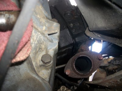
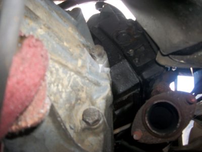
F. Once the best alignment of the turbo and pressure
chamber has been established, tighten the nut and bolt
to secure the rear brace to the turbine inlet casting
and the transmission. Make sure both nuts at exhaust
manifold are tight. See Figure 15.
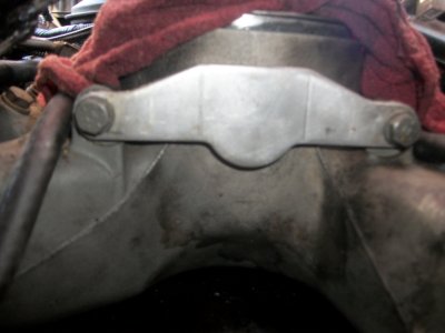
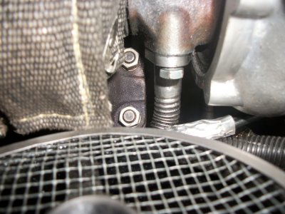
G. Install the side support brace between the turbine
inlet casting and support bracket on the intake manifold.
The end of the brace with the greater bend goes
against the bracket. See Figure 15. Use a 7⁄16 – 20 x 11⁄4
long hex bolt, 7⁄16 – 20 nylock nut, 7⁄16 – 20 stainless collet
locknut and three 7⁄16” S.A.E. washers. See Figure 16 for
correct locknut installation. Tighten nuts and bolts at
side brace and intake manifold bracket.
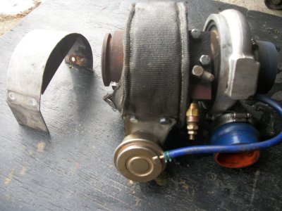
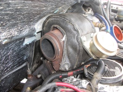
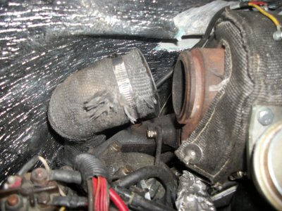
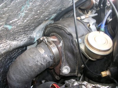
optional step: this is a good time to install a turbo blanket in place of the heat shield.i used the same one i used on chip truck:
CXRacing #1078107002413 (GT28 GT25 Turbo Heat Shield Blanket Fiber Glass Black)
why? keep that heat in to reduce under hood temps and quicker spool (increased turbo whistle) .....no one likes turbo lag!
18.Remove the turbocharger and pressure chamber
from the engine. Cover the turbo flange
opening and intake manifold openings.
19.Install oil inlet block an o-ring on turbocharger,
using two 8mm x 30mm hex bolts (bolts are
gold colored for identification) and two pairs (4 total)
of ramp lock washers. See Figure 19 for proper installation
of ramp lock washers. Install a 1⁄8 NPT x – 4 AN
elbow fitting in the oil inlet block. Use Teflon tape on
the elbow threads. Aim the elbow as shown in Figure
18.
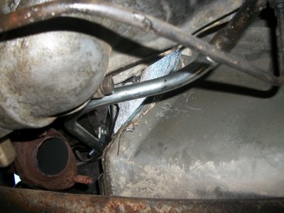
A. Run a bead of silicone sealant around the oil drain
tube about 1⁄4” up from the unflanged end. Insert the
drain tube into the grommet behind the intake manifold
while keeping the throttle cable(s) and wire loom
between the oil drain tube and intake manifold. Push
the drain tube about 1⁄2” into the grommet.
B. Install the turbocharger on the turbine inlet casting
using four 3⁄8 – 24 stainless collet locknuts and four 3⁄8
AN washers. No gasket is used between the turbo and
the casting. The upper nut on the driver’s side can be
more easily accessed by reaching between the turbo
compressor cover and the firewall on the driver’s side.
C. Bolt the oil drain tube against the flange on the bottom
of the turbocharger center bearing section. Use
a drain gasket, two 8mm x 20mm hex bolts (bolts are
gold for identification) and two pairs (4 total) of ramp
lock washers.
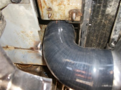
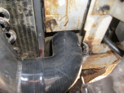
D. Place a 21⁄4” diameter hump hose and two No. 36
hose clamps onto the turbocharger compressor outlet
connection.
E. Set the pressure chamber onto the intake manifold
with 5” o-ring in place. Install the center bolt, AN
washer and sealing washer. Align the pressure chamber
and tighten the center bolt. Make sure the pressure
chamber contacts the intake manifold so no gap exists
at the junction. This assures that the o-ring is captured
and sealing.
F. Center the hump hose between the turbo and pressure
chamber, then tighten the two hose clamps.
NOTE: On C-6 automatic transmission models, check
that transmission kick-down rod does not bind or hang
up on anything in the vicinity of the turbocharger.
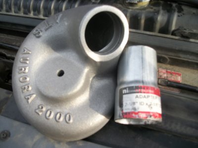
G. Bolt the anti-depression valve to the turbo compressor
inlet elbow using the original bolts. Hose nipple on
anti-depression valve must be oriented up. An optional
valve adapter is required on pre-’87 models.
H. Slide a 3” diameter by 17⁄8” long silicone hose and
two No. 52 clamps onto the compressor 11 inlet of the
turbocharger. Install the compressor inlet elbow into
the 3” silicone hose. Do not tighten hose clamps. Install
two 3⁄8” x 1 1⁄2” long studs in the two threaded holes on
the intake manifold, near the driver’s side of the injector
pump.
Install the air filter support bracket over the studs
using two 3⁄8 – 24 nylock nuts and two 3⁄8” AN washers.
Leave the nuts loose enough to adjust the position
of the bracket. NOTE: Make sure the latches are
in a raised position before tightening nuts or latches
will not clear pressure chamber.
A. Slide air filter into filter housing. The step on the
small end of the filter should extend about 1⁄8” through
the plastic housing to support and center the filter.
Push the filter all the way into the housing.
B. Position a No. 74 hose clamp over the neck of the air
filter. Place the rectangular projection on the bottom of
the filter housing through the corresponding opening
on the filter mounting bracket. Slide the filter/housing
assembly rearward in the bracket while guiding the
turbo inlet elbow into the air filter neck until it stops.
Now tighten the two No. 52 hose clamps at the turbo
and the intake elbow. Push the filter and filter housing
forward within the confines of the slot in the air filter
bracket, then latch the filter housing in place. Make
sure the front end of the filter projects 1⁄8” through the
filter housing. Now tighten the filter bracket bolts and
the No. 74 hose clamp at the filter neck.
NOTE: On air conditioned models, one refrigerant hose
passes over the air inlet elbow. To prevent this hose
from putting undue pressure on the air filter neck or
rubbing on the air inlet elbow, it can be lifted somewhat
by one of the following methods. If the hose does
not rub on the air inlet elbow, proceed to Step 20.
20.On models with a threaded hose connection
at the air conditioning compressor, carefully
loosen the nut on the hose connection just enough to
rotate the hose into a more desirable position providing
additional clearance. This can usually be accomplished
without the loss of any refrigerant. Tighten the
nut when complete. On models where the hose terminates
into a bent steel tube section and is bolted to the
compressor, carefully bend the steel tube section up
slightly to raise the hose. Slide the factory protective
sleeve on the hose to a position adjacent to the windshield
wiper motor, then tie the hose to the motor with
a cable tie wrap to pull the hose up and away from the
inlet elbow. See Figure 20,21.
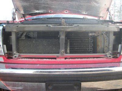
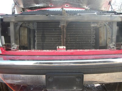
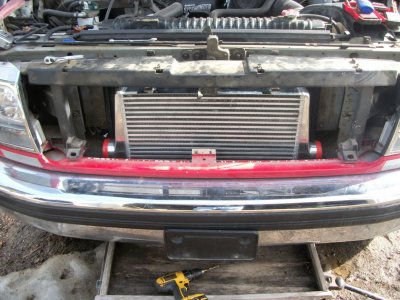
On late model vehicles where engine intake air is
drawn through a plastic duct from over the grille, the
duct must be cut just where it begins the last bend,
see Figure 22. Some early model vehicles where duct
comes from below battery may require similar modifications
if inlet hose kinks.
A. Install the factory flexible air inlet hose between the
air filter housing and factory air inlet duct. Check that
brake line tube from master cylinder does not rub on
flex hose. Carefully bend tube if required. NOTE: On
late model vehicles where engine intake air is drawn
over the grille, trim the padding away from the underside
of the hood above the air inlet as shown in Figure
23. This prevents the padding from being sucked up
against the air intake and blocking air flow.
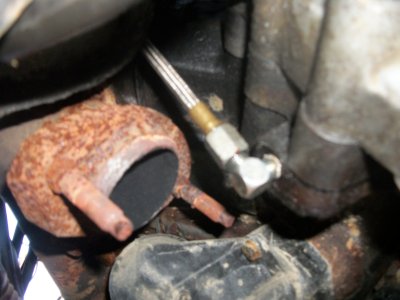
temporarily skipped: my auto meter sending unit is too long to fit.i'll need different fittings/bushings.
21.Install the factory oil pressure sender in the oil
inlet block on the turbocharger. Use teflon tape
on the threads. On early model vehicles which use the
large diameter pressure sender, install a 45° brass street
elbow between the turbo and the sender to clear the
turbo. When sender is installed, reconnect sender wire
from wire loom. Make sure wire is routed away from hot
turbo surfaces. See Figure 18.
A. Connect the turbo oil feed hose to the elbow on the
turbo center section.
B. On wastegated models, connect the 3⁄16” nipple on
the turbocharger compressor to the wastegate actuator
diaphragm (on turbine housing) using a 3⁄16 x 10” silicone
hose and two spring band clamps.
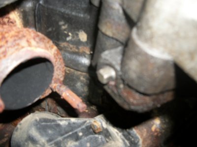
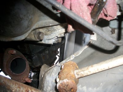
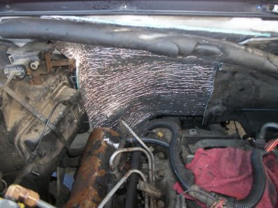
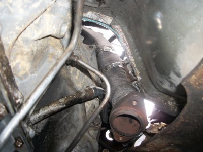
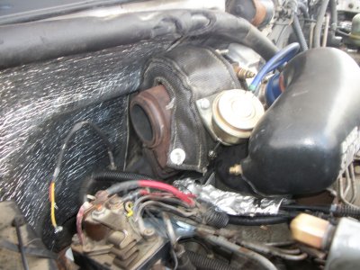
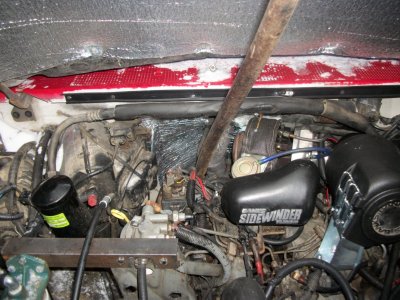
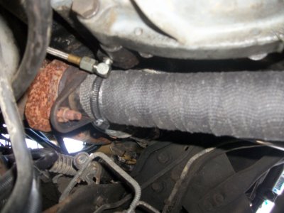
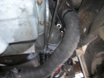
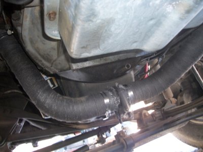
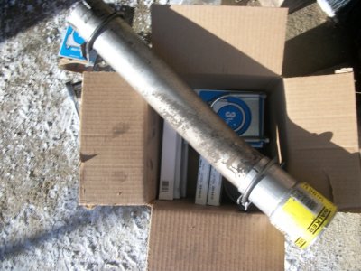
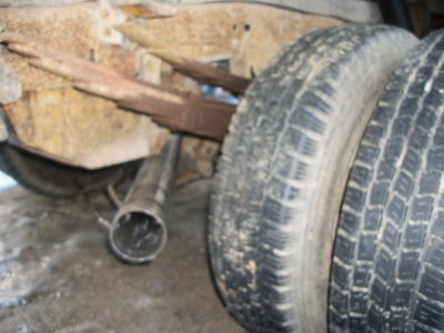
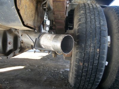
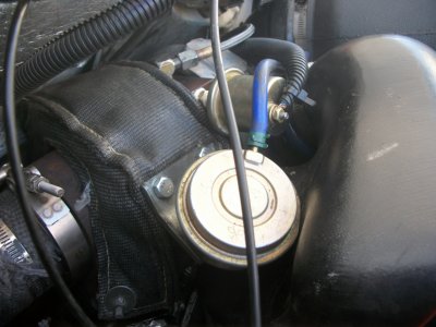
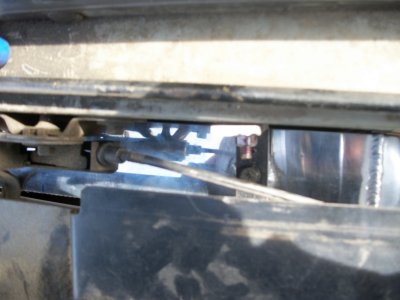
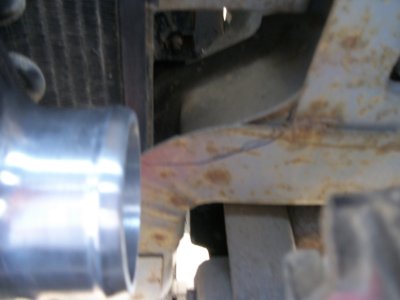
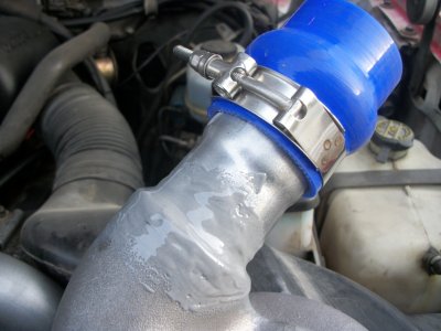
first part of 22 only.the dp install.this is where i left off.
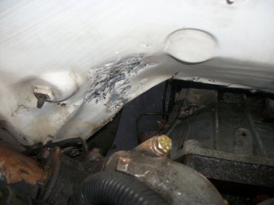
22.Install the 7” x 24” heat blanket on turbo downpipe.
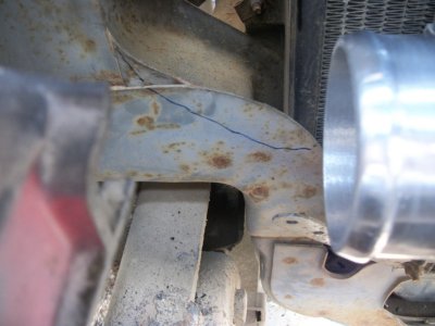
Form heat shield to the pipe to allow protection
for the firewall. Secure using wire ties provided.
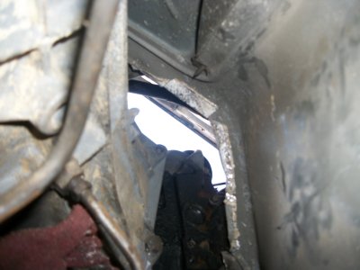
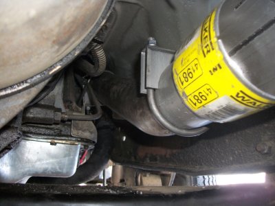
Drop the turbocharger exhaust outlet pipe between the
rear of the engine and the firewall. Start by lowering
the pipe with the flared end pointing toward the passenger
side of the vehicle (away from the turbo), then
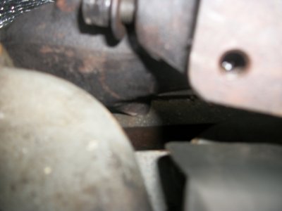
rotate the pipe clockwise as it is lowered. Install the
V-band clamp to couple the outlet pipe to the turbo.
Check that the outlet pipe is reasonably centered on
the outlet flange of the turbo as the clamp is tightened.
Leave the clamp just loose enough to allow the outlet
pipe to move slightly for exhaust system adjustment.
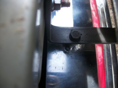
A. Remount the vacuum junction block (if removed) on
the firewall, relocating it upwards as required to provide
maximum clearance to the turbocharger and exhaust
outlet pipe. Drill new mounting holes to suit and reuse
original sheet metal screws.
NOTE: On C6 automatic transmission models, reconnect
transmission modulator hose and tube. Route hose
away from hot turbo and exhaust piping.
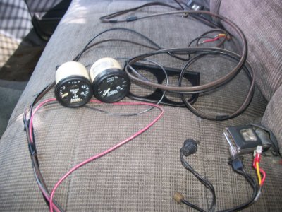
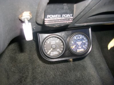
Install pyrometer (exhaust gas temperature) gauge and
any other optional instruments. Instructions for pyrometer
installation are supplied with the pyrometer instrument.
Route all wiring away from heat sources, moving
parts and sharp edges.
NOTE: If an optional turbo boost gauge (available from
Banks) is not to be installed, install a 1⁄8” NPT pipe plug in
the port on the passenger side of the pressure chamber
casting (plug is supplied with turbo system hardware).
phew!!!!
that's the last of the tough part.it's all downhill from here.bringing it to you live (almost lol) right here on channel 444!
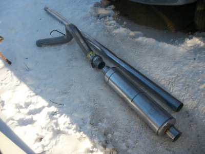
stay tuned as log truck's turbo gets finished up and then it's onto the 3.5" exhaust system very soon! hope your enjoying the the log truck show!