1993 Ford F-Super Duty XLT - "Log Truck" (new to me truck-pic heavy)

LCAM-01XA

Full Access Member
Joined
Mar 17, 2008
Posts
5,932
Reaction score
12
Location
my very own hell
so the pcm isn't switching internally then, to power/ground the correct lines to the switch.but it's operating correctly.just glowing and kinda flickering at me making me nervous that it'll soon get worse and leave me stranded while working the truck.
Aye, sure sounds like it. And you know she won't leave you really stranded unless something fails catastrophically inside the transmission, even with total loss of power you still have reverse and 2nd and non-lokcup OD, with due caution those will be enough to get you home.

im fairly sure the 12V and 14V was listed correctly.in case it matters, though i could have stated the wrong wire was lower/higher than the other.
for example when i said the red/yellow read 14V it could have been the white/lg was the 14V and the red/yellow was the 12V.
Nah, pretty sure you got them correct. R/Y should be coming from the fuse panel, which sees battery voltage, which is actually alternator voltage, which we know is around 14V with engine running, so 14V at the R/Y wire sounds about right. Why you got 12V on the W/LG idk, seems very odd to me... Can you pull the covers off the chip truck column and measure its connector voltages and compare to those of the log truck? Worst case my dashboard harness is still intact and the TCM is also plugged in, I can drop a relay in the respective spot and revive the TCM, then I can measure what voltages I get at my OD cancel switch connector - but I really don't feel like hanging upside down from the seat measuring stuff under the dash, so I'd rather avoid it if possible LOL
 

FORDF250HDXLT

The life of an Indian is like the wings of the air
Supporting Member
Joined
Dec 27, 2009
Posts
6,456
Reaction score
1,127
Location
Maine & Oklahoma
well shoot,chip trucks od cancel lines are reading the same deal.
so i decided to see if the issue was from the connector up to the od cancel switch.......no dice.same readings.just for kicks and giggles though i went ahead and traded the shift handles w/cancel buttons between trucks.
same results.chip was still reading correctly with logs handle/harness/button and logs was still glowing the light with chips.
log truck's ecm is trying to tell me something but i just don't know what it is.worse yet,now i see the switch button connectors read the same values in both trucks,i now am clueless as to how log's ecm is trying to tell me something lmao!
 

FORDF250HDXLT

The life of an Indian is like the wings of the air
Supporting Member
Joined
Dec 27, 2009
Posts
6,456
Reaction score
1,127
Location
Maine & Oklahoma
To remove your TCM. Remove the drivers side kick panel. Under the hood remove the connector bolt.

there appears to be two studs in the engine bay side.upper and lower with a plastic mount that holds it in.it appears the tcm comes out through the engine bay side,but it's hitting the inner fender so i can't pull it out all the whole way.
i was going to give up and just swap out ecms to test it this way.thought it would be cheating (though sucky as i wont learn a damn thing) but this doesn't appear to be easy either lmao.this things kicking my ass the whole way here.iv no idea on how long the thing is,but i guess im gunna try and find out by prying down the inner fender without having to remove them on each truck to save some time,but may not get so lucky.

edit;
ok.it does come out through the engine bay side and you do need to drop the inner fender down.the b....ch is too long lol.only the front half of the bolts though.those two large nuts directly up top,and the outside fender bolts and the one inside.basically so the front inner fender can tip down is all it takes (like it's cake walk or something lol.) then out she came.this is log trucks ecm.after a cup of joe i'll pull chips and try it in this truck.
if i still get a dim od light,least it points me back to wiring i suppose.if it no longer glows then i learned nothing about diagnosing it's failure for us,but such is life i guess.
 

Attachments

  • 111ecm.jpg
    111ecm.jpg
    610.1 KB · Views: 9
  • 112ecm.jpg
    112ecm.jpg
    589.3 KB · Views: 8
Last edited:

FORDF250HDXLT

The life of an Indian is like the wings of the air
Supporting Member
Joined
Dec 27, 2009
Posts
6,456
Reaction score
1,127
Location
Maine & Oklahoma
whats this? a reman in chip! (iv never removed an ecm before today.someone else swapped it out years ago) theres no telling what your going to find with these old trucks.
well i tell ya i really like this one.always have.there isn't a thing i would change about its shift points and lockup.imho it's perfect.notice this ones the part# as log trucks posted above save for the last two digits.would it be reman to it's oem specs though or some specked out to some other #? i suppose there's no way of knowing.
so after yet another cup of coffee i'll toss this in log truck and see what happens.

F450 (log truck) teca# F4TF-12B565-BA (appears to be original) - notice the "DEB0"?
F250 (chip truck) teca# F4TF-12B565-AA (REMANUFACTURED) - notice the "CAW0"?

both trucks are oem M codes (8th digit in the VIN.N/A) according to the coffee table book the 93-94 turbo idi pdf,the factory turbo engines received a "turbo spec" ecm for the E40D trans.sorry though,im unaware of its part #. just tossing that out there for those who would like to know.
i don't what they would have done differently in it's calibration,but iv often thought,you know when your in OD and when you accelerate enough to downshift,the converter unlocks,she kicks down the 3rd,then re-locks?
well i wonder if they didn't extend this unlock state duration right here so as to help keep boost up? anyway.back out to the cold.
 

Attachments

  • f250ecm1.jpg
    f250ecm1.jpg
    598.3 KB · Views: 7
  • f250ecm2.jpg
    f250ecm2.jpg
    500.7 KB · Views: 7
  • f250ecm3.jpg
    f250ecm3.jpg
    580.7 KB · Views: 8
Last edited:

FORDF250HDXLT

The life of an Indian is like the wings of the air
Supporting Member
Joined
Dec 27, 2009
Posts
6,456
Reaction score
1,127
Location
Maine & Oklahoma
confirmed.bad ecm in log truck.when swapping the ecm's the dim od light followed to chip truck and log truck was cured with chips reman ecm installed.
that's a ****** though i wasn't able to diagnose the ecm,but least i did show how to rule out everything first before blaming the ecm,as they rarely fail (as both my trucks have or will have replacements now lmao! but it's true,it's a rarity.) so make sure your rule out wiring,fuses,switches etc first anyway like i did (to the best of my ability) before jumping to the control unit.
now to see if i can source one.iv got to go put my plow truck back together now though before the pats game.:D
 

ifrythings

Full Access Member
Joined
Dec 17, 2011
Posts
734
Reaction score
485
Location
BC
You defiantly like doings things the harder way lol the TCM will almost fall out into the cab if you take the drivers kick panel off and the one retaining bolt and it slides right out. Also if you don't want to give up on diagnosing your TCM, I'll try and give you a hand figuring out what's up with it internally if you have the ambition and a few tools, let me know as I have a TCM beside me to help follow along.
 

1mouse3

Full Access Member
Joined
Nov 28, 2013
Posts
1,391
Reaction score
969
Location
il
that an you can go grab another eec-iv from the yard, flash the tune from the working one you got.
 

ifrythings

Full Access Member
Joined
Dec 17, 2011
Posts
734
Reaction score
485
Location
BC
that an you can go grab another eec-iv from the yard, flash the tune from the working one you got.

These TCM's have a masked rom in them, you can't reprogram that type of rom, but you can buy a chip that plugs into the service port and will disable the internal rom and the processor will run whatever is on the external chip.

Reman eec's aren't too expensive for these older rigs, (about 150) or you can get one from the yard, his is broken and owes him nothing so if he just wants to replace it or try fixing it and save some $$ that's up to him.

JM2C
 

FORDF250HDXLT

The life of an Indian is like the wings of the air
Supporting Member
Joined
Dec 27, 2009
Posts
6,456
Reaction score
1,127
Location
Maine & Oklahoma
im not sure how these are accessed in the older trucks,but these pics should show how it is in the 9th gen trucks.as you can see,there is a plastic shroud/ecm mount with top and bottom holes.these holes are for two studs,so both nuts must be removed and this comes off from the engine bay side.this mount is right behind the wire connector if you will.
as you can see in the other pic,i left the plastic kick panel off still from running wires up and around for gauges/keyless entry.see that massive piece of metal? the ecm is behind that.so not only could you not bring it out from this side,you can't even see it! lol. there is no reason to remove the interior kick panle either actually (i just had it off already so i snapped ya pic) as there is nothing needed to unbolt the ecm from this side.100% no access to it from in here.
 

Attachments

  • 113ecmmount.jpg
    113ecmmount.jpg
    676.4 KB · Views: 24
  • 114ecmbehind.jpg
    114ecmbehind.jpg
    624.6 KB · Views: 18

FORDF250HDXLT

The life of an Indian is like the wings of the air
Supporting Member
Joined
Dec 27, 2009
Posts
6,456
Reaction score
1,127
Location
Maine & Oklahoma
tonight on log truck.............it's a break from electrical work with some good old school shift kit install fun! the installation of transgo's E40D-HD2-D reprogramming kit (shift kit) begins so this old log truck shifts like a work truck and not a car.;Sweet


the instructions & the video.
http://transgo.com/E4OD_HD2Video.html
 

Attachments

  • a cover.jpg
    a cover.jpg
    666.1 KB · Views: 318
  • b page 1.jpg
    b page 1.jpg
    705.5 KB · Views: 322
  • c page 2.jpg
    c page 2.jpg
    752.7 KB · Views: 317
  • d page 3.jpg
    d page 3.jpg
    728.3 KB · Views: 316
  • e page 4.jpg
    e page 4.jpg
    733.1 KB · Views: 320
  • f page 5.jpg
    f page 5.jpg
    717.5 KB · Views: 316
Last edited:

FORDF250HDXLT

The life of an Indian is like the wings of the air
Supporting Member
Joined
Dec 27, 2009
Posts
6,456
Reaction score
1,127
Location
Maine & Oklahoma
it all begins with a good old fashion atf bath.......ah there's nothing like some atf in the hair.ah come on,it's the shampoo of real men!
yes i have a new 4r100 pan with drain plug going in with this kit and flush.my mama didn't raise no fool.;)
attachment.php


drop that solenoid pack.don't be a sissy now.your not gunna brake it.(well ok.go real easy on unhooking that connector.remember no screw drivers!!!! press in from the front/open side you can get to,and pull up at same time.flush the **** out of it with cleaner first though.) but once the bolts and nuts are off.simply reach up there and press down on the plug while pulling down with the other hand.she'll come.it's just an o-ring.
attachment.php


spin them bolts out of that accumulator body.leaving the two nuts to hold 'er there for ya until your ready to drop it in your pan.
attachment.php


do the same with the main valve body.yeah,it's a lot.hang in there.you've almost got 'em.........whoah caution!
take note of those two bolts towards the inside you see there....yeah those ones! don't touch those or you'll wish you didn't with the upper case of the main body coming down along with a couple check balls falling out on you and likely being lost forever lol.
also watch the video,he shows you which bolt to rob temporarily from the front,to help hold up the rear.do this now also or regret it forever!!
remove all but those two bolts and the two nuts.like the others,once the shower of atf subsides a bit,go ahead and remove the two nuts and lower the main body into your pan.
attachment.php


bring these parts to be modified inside unless your a lucky SOB with a heated shop!:D
attachment.php

attachment.php

attachment.php


starting with the accumulator body,notice iv got the slot where noted in the directions of the accumulator body.therefore no drilling is required for mine.
attachment.php


flip her back over and start gutting her.starting with the 3rd piston.note the upper springs are the ones removed.the orange ones along with a white one as noted are going in,in their place(just toss the oem ones over your shoulder.you don't want them for anything.;) )
attachment.php


mod that 4th piston.same deal here.oem springs are up top (to be going in the trash) with the new orange set going in.
attachment.php
 

Attachments

  • 1drop pan.jpg
    1drop pan.jpg
    637.4 KB · Views: 478
  • 2lower s-pack.jpg
    2lower s-pack.jpg
    681.2 KB · Views: 463
  • 3loweraccumulator body.jpg
    3loweraccumulator body.jpg
    671.2 KB · Views: 462
  • 4lower mainv-body.jpg
    4lower mainv-body.jpg
    623 KB · Views: 460
  • 5 s-kit.jpg
    5 s-kit.jpg
    616.1 KB · Views: 463
  • 6 s-kit2.jpg
    6 s-kit2.jpg
    630.9 KB · Views: 457
  • 7 s-kit3.jpg
    7 s-kit3.jpg
    656.6 KB · Views: 448
  • 8accumulator v-body with slot.jpg
    8accumulator v-body with slot.jpg
    297 KB · Views: 455
  • 9mod 3rd piston.jpg
    9mod 3rd piston.jpg
    735.3 KB · Views: 452
  • 10 mod4th piston.jpg
    10 mod4th piston.jpg
    707.4 KB · Views: 456
Last edited:

FORDF250HDXLT

The life of an Indian is like the wings of the air
Supporting Member
Joined
Dec 27, 2009
Posts
6,456
Reaction score
1,127
Location
Maine & Oklahoma
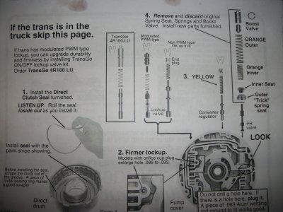
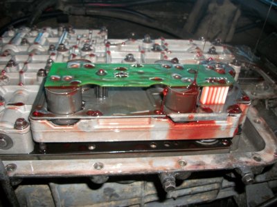
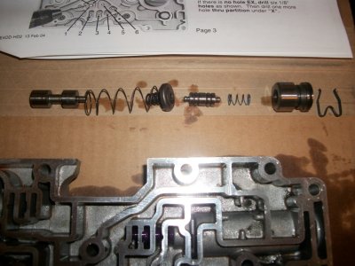
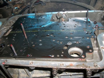
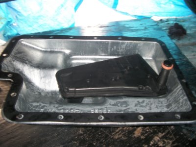
ah nuts.my bad on this one! better check them instructions.i was having such a good time,i was forgetting i was taking pics.i had installed the first part of this assembly here.once installed (it was a bit of a ****** so i didn't want to pull it for the pic lmao.sorry!) i then snapped ya one.
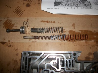
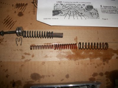
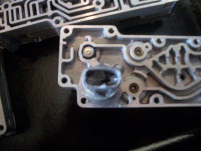
basically though what i missed to show,was replacing that regulator valve.the oem one was a bright colored purple.you replace than with the new steel one supplied in the kit.reuse the little spring and then set that clip back in (yeah i had this all done when i remembered the cam right here.no biggie.the instructions are clear.) then simply install the springs as shown.
attachment.php


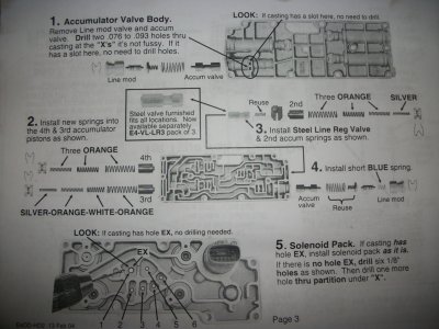
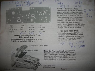
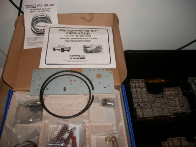
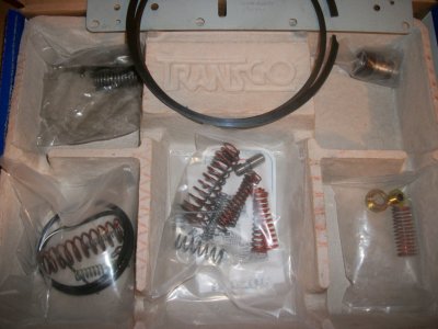
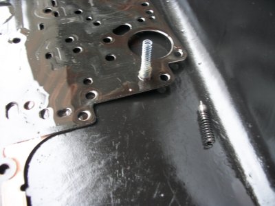
install blue spring as noted in step 4 of instructions.final mod of accumulator.
your adding this short blue spring where there was no spring at all currently.
(find this particular short blue spring in the same pack of the other accumulator springs.not to be confused with a blue spring in other package.)
attachment.php


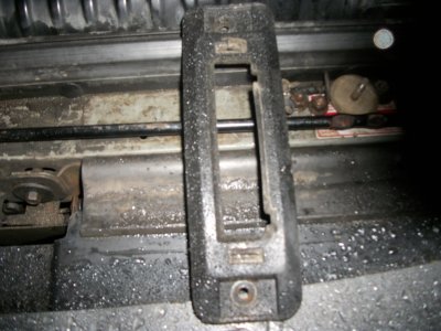
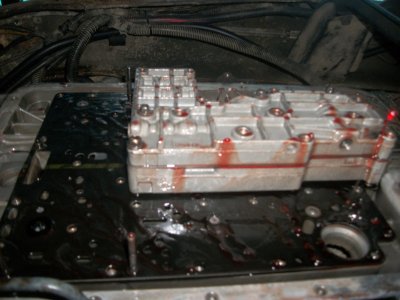
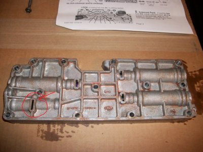
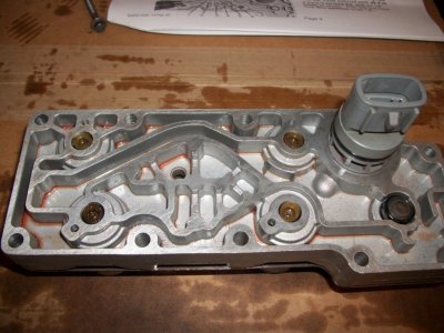
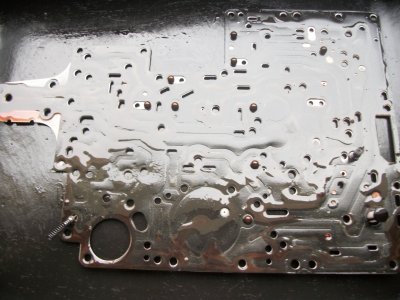
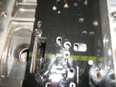
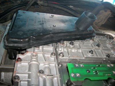
moving on to the solenoid pack modifications.
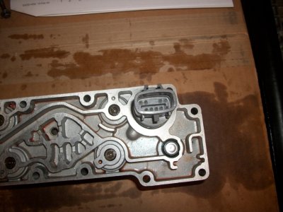
notice the EX hole in my pack.no drilling required.see all those slots as well compared to the instructions? see how all those are able to flow atf through there.
attachment.php


additional.take note
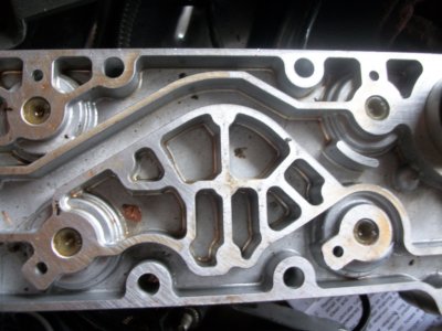
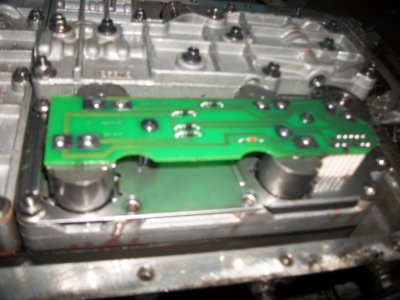
this great time to clean the s pack pins.
this is the main line of communication between the trans controller and your transmission.these pins can't be over clean.take your time and make them shine.
upon reasonably,just before plugging it in,apply a nice dose of Permatex 22058 dielectric tune-up grease.
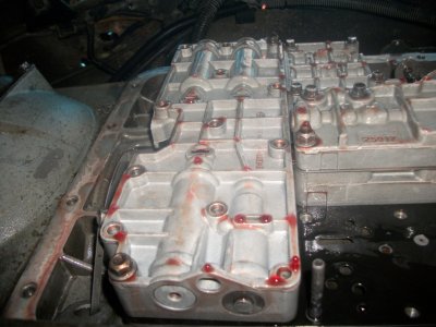
attachment.php


side note and pic;
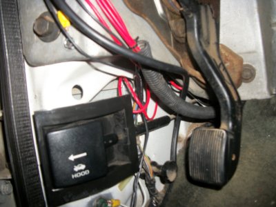
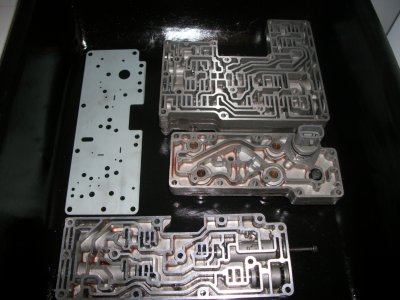
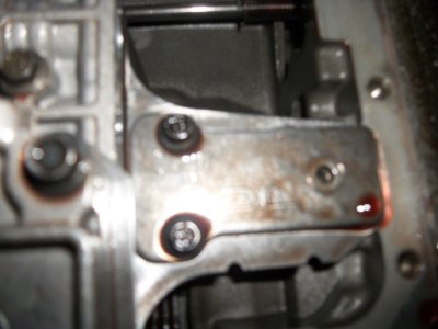
check out this pic.here is a pack i pulled from my f250 (i had to replace that due to extremely corrosive pack plug that i just couldn't ever get clean.) and it doesn't have hole EX.notice how all these passages are full as well.no atf can flow up around there.that s-pack would be one that would require the modifications.
i have a transgo tugger kit installed in that truck (by trans shop during reman) when i went to replace the pack a few months ago,i didn't know to look to see if the new pack i put in required modding.come warm weather i'll take a peek and mod it if needed.
(yeah i know this ones dirty.it's junk.i pulled this out of the junk pile for ya to compare.)
this makes ya wonder, if this was the pack in the trans during a reman with the install of the tugger kit,then why wasn't it modified? the bad electrical pins should have been discovered during the reman as well too anyway,with a new pack going in at this time.it's as if this pack went without proper inspection all the way around by the trans shop unfortunately.
attachment.php


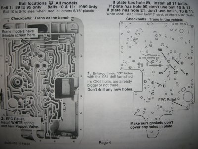
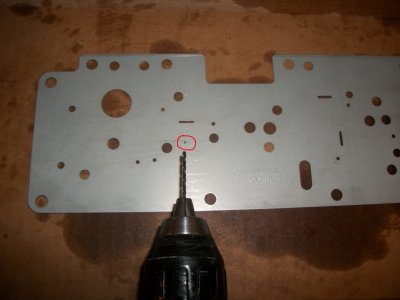
now it's time to figure out what you want for shifts.step it up and make 'em like a man shift.don't girl out now and go too easy ya sissy.so big or go home!
ok.seriously.do be a bit careful.you can always make the holes larger if one or more shifts are bit too girlish still.that requires draining the juice again so do consider an 4r100 pan.
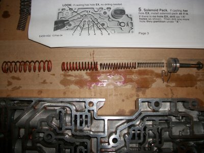
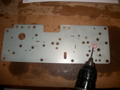
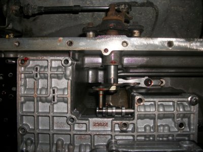
2nd.for diesel .110-116. using a chart i quickly googled,and as you can see i did a little scribbling of what i found here on the sheet.
http://www.carbidedepot.com/formulas-drillsize.htm

i went with a 7/64 drill bit here.
attachment.php


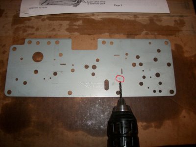
3rd.i used the supplied drill bit (this is the one shown pointing to the holes in the pics.) which is for page 4.it say's it's an .081.yeah it's on the large end of things for this one,plus this old gal has 5:13's uh oh......im not scared,but probably should be lol.
attachment.php


4th.give me a nice firm final shift into OD too.i'll like it.i went with a 3/32 bit here.
attachment.php


this completes the steps i'll be doing for my diesel work truck.the parts are ready to go back in the truck once i perform the instructions on page 4 tomorrow. yes i'll have the pics for ya of course! seriously,you got worried?:D
attachment.php


stay tuned and keep it right here on channel 444 log truck as i take this E40D sissy shifting slush bucket and transform her into a crisp shifting beast.;Sweet
 

Attachments

  • 11 mod reg line valve.jpg
    11 mod reg line valve.jpg
    765.8 KB · Views: 440
  • 12 install blue spring -step 4.jpg
    12 install blue spring -step 4.jpg
    719.9 KB · Views: 445
  • 13 s-pack with hole EX.jpg
    13 s-pack with hole EX.jpg
    717.1 KB · Views: 438
  • 14 2nd shift calibration plate mod.jpg
    14 2nd shift calibration plate mod.jpg
    200.5 KB · Views: 435
  • 15 3rd shift calibration plate mod.jpg
    15 3rd shift calibration plate mod.jpg
    217.7 KB · Views: 433
  • 16 4th shift calibration plate mod.jpg
    16 4th shift calibration plate mod.jpg
    216.3 KB · Views: 441
  • 17 good time to clean the s pack pins.jpg
    17 good time to clean the s pack pins.jpg
    662.1 KB · Views: 438
  • 18 parts modified and ready for installation.jpg
    18 parts modified and ready for installation.jpg
    694.7 KB · Views: 427
  • 50oldf250s-pack.jpg
    50oldf250s-pack.jpg
    621.9 KB · Views: 435
Last edited:

asmith

Full Access Member
Joined
Jan 28, 2012
Posts
672
Reaction score
217
Location
Atascadero, Ca
once your done with this, would you like to take a break from the cold and come out to warm california for a couple days? 80 degrees here today. you can redo the trailer wiring on my truck!! it is on my to-do list. have no idea what the PO did, except that it is wrong. all the wires are cut and butt jointed and switched around. seriously nice work so far, you do very clean professional work.
 

trackspeeder

Stone crusher.
Joined
Dec 21, 2003
Posts
4,091
Reaction score
232
Location
North Branford. CT
Everything looks good. Hey, least you got a clean ATF hair wash. You should try some dirty nasty stuff. I swear it smells for days.

I see you did your homework and did not remove those two bolts. You missed out on the excitement of loosing your balls.

Most importantly, you didn't drill the holes big. Most people will go big first then ***** about the harsh shifts. You can go larger but you can't go back.

Remember to torque all VB bolts 80-100 inch pounds. then drive it like you stole it.:D
 

FORDF250HDXLT

The life of an Indian is like the wings of the air
Supporting Member
Joined
Dec 27, 2009
Posts
6,456
Reaction score
1,127
Location
Maine & Oklahoma
tonight on log truck.....................log truck feels the gears with the conclusion of the shift kit install, along with some fresh lube, filter and new pan w/drain plug.


now is the real fun part....not!
caution!
carefully,carefully,and carefully,remove the bolt you robbed earlier to hold up the rear of the separator plate along with the two and the plate labeled "up"....while keeping your hand spread out as much as possible so you can lower the plate down and off the studs as gently and smoothly as possible.careful!!! springs,check balls and other small items such as poppets and screen can go flying if you try and rush it.careful now.careful.did i mention you should you should be careful?
attachment.php


next.it's time to consult the instructions to see what you need to do.
with mine,i had the hole at 90.with a hole here,it then tells you not to use balls 10 and 11 if this is case.this appears to be letting you know how it is,rather than do anything about it.as the ball 10 and 11 are not even there anyway.
so checking out the holes at the three "D" locations,i found the provided bit was the same size as all these holes on mine.so nothing required here.(yes i know,some of mine "appear" to be out of place over on one side there.this is just because a couple over there can roam from one position to the other here.follow the chart and move them if it makes you feel better.always follow the chart per year if you dropped them. i didn't disturb them.)
attachment.php


lastly,following the instructions and replace the spring and poppet.
tip: hold it with a good dose of petroleum jelly.
now it's ready for install.
attachment.php


install carefully,carefully,and more carefully.watch that everything sticking up in the air from the plate,finds it's home or.......i dunno.lol just make sure!likely it could lead to severe trans damage.best case,it just doesn't work and you need to fix it.so make sure.you'll know when they all line up correctly.
follow how you removed them.place the plate "up" back on with just the 2 bolts and the one you robbed at the other end to hold it all up.
attachment.php

attachment.php


phew! that was a ****** uh? haha.take a breather.the stressful part is over.now back to more enjoyment as the rest simply flows back together with ease.
so paying attention to line up that gear selector pin as shown,bolt up the main body.
You must be registered for see images attach


ready that cleaned up solenoid pack with those now spotless and shiny electrical pins,and pack these pins now with the Permatex 22058 dielectric tune-up grease.also lube up the o-ring with petroleum jelly.firmly and evenly,press the body up to the separator plate.it should "pop" into place.bolt it up along with the accumulator body and don't forget your new transgo accumulator plate (with those 2/3/4 shift holes you drilled out earlier.) finish bolting up all these bodies now.she's all back together and modified.
attachment.php

attachment.php


lube up the o-ring on the filter and press into the hole.making sure first,that the old o-ring came out with the old filter if your replacing it.
firmly press into position.petroleum jelly applied to the gasket also helps hold it all lined up for you as you install.
attachment.php

attachment.php

attachment.php
 

Attachments

  • 19 seperator plate.jpg
    19 seperator plate.jpg
    737.6 KB · Views: 420
  • 20 seperator plate removed.jpg
    20 seperator plate removed.jpg
    704.8 KB · Views: 415
  • 21 new epc releif spring and poppet .jpg
    21 new epc releif spring and poppet .jpg
    603.9 KB · Views: 412
  • 22 install main body.jpg
    22 install main body.jpg
    747 KB · Views: 3
  • 23 ready the pack.jpg
    23 ready the pack.jpg
    562.6 KB · Views: 4
  • 24 bolt .jpg
    24 bolt .jpg
    577.9 KB · Views: 406
  • 25 bolt.jpg
    25 bolt.jpg
    558.4 KB · Views: 405
  • 26 install accum and pack.jpg
    26 install accum and pack.jpg
    610.3 KB · Views: 406
  • 27 ready new pan filter and gasket.jpg
    27 ready new pan filter and gasket.jpg
    628.2 KB · Views: 400
  • 28 install gasket.jpg
    28 install gasket.jpg
    694.6 KB · Views: 406
Last edited:
Top