1993 Ford F-Super Duty XLT - "Log Truck" (new to me truck-pic heavy)

FORDF250HDXLT

The life of an Indian is like the wings of the air
Supporting Member
Joined
Dec 27, 2009
Posts
6,456
Reaction score
1,127
Location
Maine & Oklahoma
the electrical work continues......

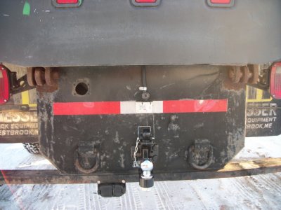
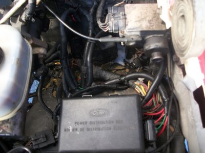
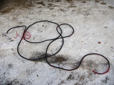
so had to move equipment around and ready chip truck for plow duty for the storm coming in,but i did manage to ready log truck with a tow harness so she'll have the tow package like any sensible person with an f450 would automatically make sure it included from ford lol.

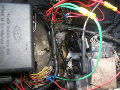
didn't have time to snap pics,but i did run it as well.though no time left to hook any of it up.that's ok though,as this was the majority of the work.now i'll have everything on devoted trailer circuits so it's as easy as wiring them on to the dead ended wires and connecting to the new tow plug out back.
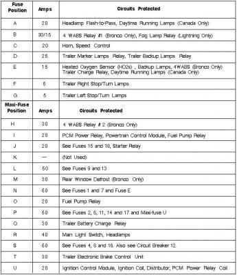
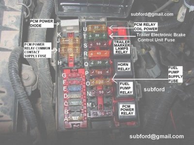
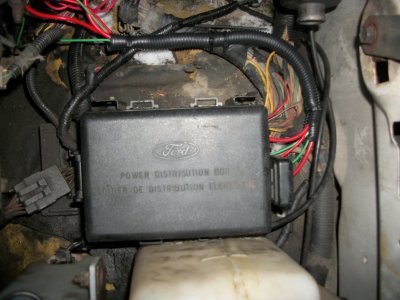
i do still need to find the two wires (green and a yellow) which are on devoted fuses up in the power distribution box.each on a 5 amp fuse.i'll double check to see if pulling the fuses kills the stop/turn signals out back on the truck.it shouldn't as it says they're for trailer.then if thats the case,it's just a matter of finding those,and tapping them onto my two 14 awg wires i ran.if they do however kill the trucks stop/turn then this means,i needlessly ran devoted 14 awg wires and could have just tapped in at the rear junction.
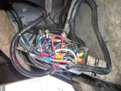
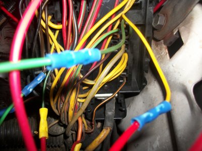
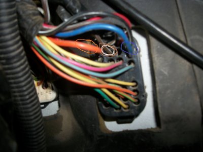
BLUE = brake 10awg.
ORANGE = 12V+ (key on/run) for battery charge.10 awg.
BROWN/WHITE = running lights.10 awg.
BLACK = ground (this is already run) 10 awg.
RED/YELLOW = backup lights.missing.no where to be found.easy fix however.i'll tap into the trucks backup lights (which is black/pink) at the tow plug/firewall side,and have this trigger a fused relay that i'll install and feed the backup of the tow plug on a devoted 10 awg i ran for it.
YELLOW = left stop/turn
GREEN = right stop/turn

edit;
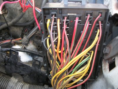
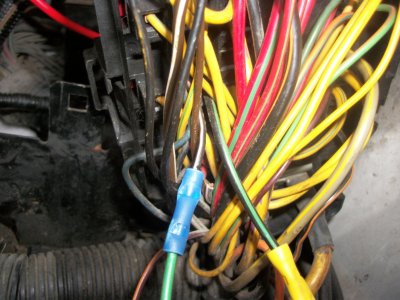
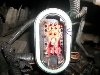
see the yellow and green wires at the very bottom of the in cab plug?
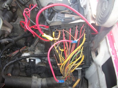
notice the blank pins on the firewall side?
i think i just found the stop/turns right there.i'll test 'em tomorrow.
 

Attachments

  • 99tow.jpg
    99tow.jpg
    753.7 KB · Views: 11
  • 100tow.jpg
    100tow.jpg
    798.5 KB · Views: 8
  • 98towb.jpg
    98towb.jpg
    257.9 KB · Views: 13
  • 97towb.jpg
    97towb.jpg
    193 KB · Views: 12
Last edited:

laserjock

Almost there...
Supporting Member
Joined
Nov 20, 2012
Posts
8,841
Reaction score
3,130
Location
Maryland
You don't mess around with wire sizes! ;Sweet

I understand the heavy wire for the brakes and the battery charge but thats some serious wire for the lights.

When I redo mine, I would like to run the bundle of wires all the way back and put the connections under the hood like you are doing as well. It just makes good sense to me. Yeah, its more wire and yeah the drivers side frame rail is already a little cramped with brake lines and fuel lines and the wire harnes but I think it's worth while. I'm also eyeballing that back-up camera.... I see possiblities for that with those of us who don't always have someone around to help hitch up.

Great build. Love the upgrades.
 

FORDF250HDXLT

The life of an Indian is like the wings of the air
Supporting Member
Joined
Dec 27, 2009
Posts
6,456
Reaction score
1,127
Location
Maine & Oklahoma
yeah with such a long truck i didn't wanna mess around.this way here i can always tap into some aux work lights at the rear of the bed too without worry.the backup lights was due to the long run on the truck and i didn't bother to check out what the dual aux lights on the dump trailer are,and look into amp draw etc.just easier to run 10 with that too and not worry about it.didn't want any regrets latter on and pulling,re-running larger wires for future add-on lights and stuff.the stop/turns was an easy choice to just run 14awg as there wont be any need to tap into those for anything serious.
yes,the backup cam right up over the hitches sure helps to hook up.big time saver when alone.

no time for anything today.i had to plow and then watch the pats.....lose.:(
 

FORDF250HDXLT

The life of an Indian is like the wings of the air
Supporting Member
Joined
Dec 27, 2009
Posts
6,456
Reaction score
1,127
Location
Maine & Oklahoma
ok so tonight on log truck..... getting the backup tow setup all updated now with the modern multi plug,updated hitch and balls,rear view cam.

however,that orange wire is a fake.not only is it a slightly lighter gauge than the one on the f250 w/tow package,but she's not hot with key on either.so the 30 amp trailer battery charge circuit has nothing hooked up to it,and i think a dud 12 awg wire may be capped off on each plug.

so looks like a devoted key on/run relay setup will be required here along with a relay triggered for the backup trailer circuit.no problems with doing either of those.
unfortunately those bottom green & yellow wires are not trailer turn signals off the two devoted trailer stop/turn signal fuses either.not sure this ones worth messing with.likely will just wire in the trailers stop/turns in with the trucks out back,unless someone knows where to find the lines from those two fuses coming out of the box.
real close now.it's amazing how much longer doing this kind of stuff takes when it's so damn cold out.ugg.i hate it.need a 40' heated shop!
 

Attachments

  • 101tow.jpg
    101tow.jpg
    648.8 KB · Views: 26
  • 102tow.jpg
    102tow.jpg
    769.6 KB · Views: 23
  • 103tow.jpg
    103tow.jpg
    673.3 KB · Views: 25

FORDF250HDXLT

The life of an Indian is like the wings of the air
Supporting Member
Joined
Dec 27, 2009
Posts
6,456
Reaction score
1,127
Location
Maine & Oklahoma
ok,so you know what i'll do here then.rather than run devoted fuse holders and relays and who knows what with the trailer stop/turn signals.is to just wire up the power distribution box.big power line is already right there,the fuses are there for everything i need,going unused and there are unused relay ports as well.so i'll simply unbolt this sucker and wire it up for for fused relays right in it and this way too,i can see about those devoted fused stop/turn circuits to feed my dual 14 awgs i run for them.
i'll do this "right" and take detailed pics for everyone to copy who also don't have tow package.
so the blue brake line,and the brown/white fused/relayed trailer running lights are fully hooked up.so no need to mess with those.simply snip those off inside the cab side,and butt connect the new lines run to them and done for those two.for the rest i'll tie 'em in to the blank spots in the box tomorrow and post detailed pics,to make this easy to follow.
 

Attachments

  • 1993EngineCompFuseBox.jpg
    1993EngineCompFuseBox.jpg
    91.3 KB · Views: 20
  • EngineCompartmentFusePanelwithkey-1.jpg
    EngineCompartmentFusePanelwithkey-1.jpg
    75.5 KB · Views: 86
Last edited:

FORDF250HDXLT

The life of an Indian is like the wings of the air
Supporting Member
Joined
Dec 27, 2009
Posts
6,456
Reaction score
1,127
Location
Maine & Oklahoma
tonight on log truck......the electrical fun continues as i draw near to having a complete tow package install.


ok after taking a half hour to pile on layer upon layer of cloths,so i could hardly move, it was time to finish this mess up.so i pulled the PDB (power distribution box) up and out and flipped the old gal over to access her working side so i could alter it and make use of it for my tow package.
so for our idi trucks,we have no use for the fused and relay circuits labeled in my '93 users manual as " fog lights (lighting only)" relay #1 (upper top right) nor the "fuel pump" relay #4 (4th relay down)
so these are perfect to rob and make use of for;
ORANGE = 12V+ battery charge when key on run.
RED/YELLOW (though not run at all.known as PURPLE at the tow plug end) = backup lights.
so starting with the top circuit.this ones super easy and perfect to use.FUSE Q as noted here in the pic and it's known as fuse #18 in the users manual.this is the 30 amp "trailer charge" fuse and it powers the upper relay! yes.how perfect!
so snip off the dead ended orange wire as low as possible so as to crimp on a butt connector here and hook up the devoted line you ran out to the tow plugs red wire,to this wire.
the yellow wire is feed.it is feed trough the 30 amp fuse as noted above.the black wire is the ground.the last wire,the brown one as you can see is the trigger.cut it.we need a new trigger.a power line when the key is in the run position (or if you prefer,a switched power source of your own to turn on the connection whenever you want.i strongly suggest the same power source however,or at least a power source,only with key turned in run to run up to your toggle.this way you leave the toggle on,the key still turns it off for you.)
now also snip the dead ended brown wire with stripe (i think its just another lighter shade of brown.i forget and the pic is unclear.but it's clearly the last line to this relay,directly above the black one.)
i fed this one a power when in key run,that feeds fuse K and known as #11 in the '93's users manual.apparently unused.i did however leave power going to it,as you can see,and just tied in.
that's all there is to this one.the other ends of the wires you just cut are dead ended someplace.who knows where.somewhere under the steering column i suppose.go ahead and cap them off for extra safe measure though.battery charge for dump trailers battery......complete.on to the next one.

you may not need to worry about this one,but it sure will be nice to have a hd backup light system,especially for such a long truck that will have a backup alarm,dual aux backup lights (and i see two angled ones down under the truck they had on the reg system to help shine up the sides of the truck.-i like that idea! i'll change out the bulbs or replace these lights) along with dual aux backup lights on my dump trailer.so to me,this was well worth running another relayed 10 awg line for.here's how i rigged this one in,making use of the "fuel pump" relay.2nd relay up from bottom.
snip off the dead (on idi trucks only!do this to a gas truck,and you'll be going nowhere fast lol.) large black with green stripe wire and tie onto your devoted wire run out to your center pin wire of the 7 prong tow plug.purple.
so again,you need a new trigger.this ones just as obvious.you want this line to power up when you place the shift lever in R.so just tap into the backup light line that's used for backup lights of your truck.this ones a black with pink stripe on my '93.keep it connected to the rear and just run a line up from it also,for your new relay trigger.hook it onto the black with white stripe wire it looks like as shown in the pic.
so what fuse is this relay on you may be asking? well conveniently the one labeled in the owners manual as "trailer backup and running lamps" the 25 amp fuse in D position according to the above pic,and known as fuse #4 in the manual.yeah.perfect yet again.
now just make a note in your owners manual of the new relays.run a line through them indicating they no longer represent those and write in the new labels "trailer battery charge" and "trailer backup" and your done.

lastly,i then wanted to make sure if my trailers stop/turn signals short out,that they blow those two devoted fuses as shown above and leave the trucks stop/turns in working order.
F and G (he shows dual 10 amps.they are supposed to be 5 amps each fyi.) they are fuse numbers #6 and #7 in the owners manual and it calls them "trailer LH stop/turn lamp for the upper #7
and "trailer RH stop/turn lamp for the lower #6

im not sure yet how to make sure these work as this is where i ran out of time.
first,i didn't mark my 14# awg wires,so i'll have to ohm them out and mark them up at the firewall so i know left and right.no biggie.then it may be just a matter of hooking them up accordingly to the two lines i extended out for them off the yellow and green lines as shown.
i saw the green and yellow wires dead ended down at the firewall side as stated before.so i figured id just tap in up here where it's easier and leave those lines dead ended to nowhere in the cab.anyone know is this is right? i'll temp hook 'em in and hook up to something and then see if iv got brake lights and blinkers i guess,then if so,remove a trailer stop/turn fuse to see if kills them but the trucks should still work.this should work like this best i can tell.if so,im done.crimp,wire loom,tie and call this tow package complete.if not,it's back to the books to see what iv got to do lol.getting close to full tow package now boys!;Sweet
 

Attachments

  • 104pdb1.jpg
    104pdb1.jpg
    724.3 KB · Views: 8
  • 105pdb2.jpg
    105pdb2.jpg
    707 KB · Views: 8
  • 106pdb3.jpg
    106pdb3.jpg
    717.4 KB · Views: 7
  • 107pdb4.jpg
    107pdb4.jpg
    732.1 KB · Views: 8
  • 108pdb5.jpg
    108pdb5.jpg
    695.7 KB · Views: 10
Last edited:

FORDF250HDXLT

The life of an Indian is like the wings of the air
Supporting Member
Joined
Dec 27, 2009
Posts
6,456
Reaction score
1,127
Location
Maine & Oklahoma
tonight on log truck.......enough of this electrical wiring.im seeing cross eyed and color codes in my sleep!

so today i finished up with everything.i had forgotten i had already tested those green and yellow wires for blinkers earlier on.so no wonder i still didn't have stop/turns when i hooked up the chipper to test.
so this means those wires from the multi switch (left and right stop/turns) which are orange w/blue stripe and green w/orange stripe only go out to the rear of the truck on the non tow package setup,and wherever they get tied together (up in the column some place i guess) with the tow package,they are dead ended.ran,but not hooked to go out to the PDB on non tow package trucks.so rather than dig into the PDB again to grab these wires,i easily found them entering the box and sniped them right there.simply tie into (but leave connected) the wires going out back to the truck lights and hook them to the PDB yourself.this way they will pulse your meter through the fuse and you'll know you've got it with the blinkers on.then just test the new wires running out back for left and right and crimp when right.pull the fuses and only the trucks will still flash.if she shorts,out goes that trailers stop/turn on that side only.isolating the issue while maintaining the other side and keeping the trucks lights issue free for max safety and correct tow package hook up.finished up with one last wire loom run w/ties and its all she wrote.who would of thought an f450 would leave the assembly plant without the tow harness.i still can't get over it,but she's got it now.
mission tow package........completed.;Sweet
 

Attachments

  • 109pdb6.jpg
    109pdb6.jpg
    785.9 KB · Views: 9
  • 110pdb7.jpg
    110pdb7.jpg
    629.5 KB · Views: 8

trackspeeder

Stone crusher.
Joined
Dec 21, 2003
Posts
4,091
Reaction score
232
Location
North Branford. CT
Looking good man.:D Your crossed eyes will return to normal in a couple of days.LOL

One thing to remember. Trailer tow is an option on FSuperduty, like the rest of the F series. If it wasn't ordered they didn't instal it.
 

FORDF250HDXLT

The life of an Indian is like the wings of the air
Supporting Member
Joined
Dec 27, 2009
Posts
6,456
Reaction score
1,127
Location
Maine & Oklahoma
thanks.
so i cleaned up the rest of the e40d harness.with just down at solenoid pack plug and the plug that enters the PDB from the trans left.i see they replaced the bulkhead connector already.all looks good.

so on the ride home with the truck at night (only time iv driven it.right on purchase day) i noticed the OD light was on very dimly.about half as bright as when the fuse or relay is pulled,which is about half as bright when you turn OD off.
iv hunted all around with no luck so far of finding a short.i was kinda hoping it was a short in the fuel filter heater line since that connector leaked and was smoking when hooked up! but no go.i snipped the wire right off coming out of the PDB so it's dead all the way over.still have the dim light.
i checked the 20 amp maxi,the relay of course first and all good there.iv got battery power right at the.....oh i dunno pin #16? i guess it is.the power feed at the trans ecm anyway.
hey,did you know if the anti lock brake 20 amp maxi is taken out,it also kills power to the ecm? odd stuff lol.
anywho,i then inspected and cleaned up the ecm ground wire,which i learned was the ground right there behind the drivers side kick panel.still a very dim light.i tried the diode from my chip truck and still no dice either.
i then fed what i knew was a 100% clean power line to pin '87 in the PDB which is the line that run to the ecm,and same exact thing.
i inspected the trans harness from head to tow and can't find any fault.
the tach sensor is a little skippy at idle.i traded them in trucks and the dim light didn't follow to chip,but it did get the jumpy tach at idle.
with good tach in log truck,the tach was smooth but the light still dim.
so i'll order a new tach for log truck as no doubt that probably means the sensor is on it's way out.don't need it failing when working.
the trans in log truck was working just fine,but the dim light generally meaning the ecm not getting the power it should concerns me and of course i need to fix it now,before it leaves me stranded.
i did try the OD button in chip truck too.first thing i tried was to check to see if it was just the light/button issue cus the trans was working perfectly fine.but it worked perfect in chip truck.

it's extremely dim.like a little glow.again 1/4 the brightness when canceling OD or half the brightness when pulling the fuse or relay.
in day time,i have to cup my hands around it to see it glowing.
it does have a slight flicker to it as well.-thats what made me think of that smoking connector in the fuel puddle of that filter heater when i got the truck home and decided to totally kill that whole line.the reason i thught id do this,is because i plugged off the filter heater as previously shown here,and it gets its power from the same source.
when you first start the truck,it takes about 10 seconds until it begins to glow.
the cancel button does work and it does kick out OD as it should (unlike when a fuse or relay is bad.the button will be brighter than what iv got,and the button will then do nothing whenever either of those are pulled.)
the trans is not in limp mode and works perfectly (as perfectly as a e40d can without a shift kit lol.)


whats next? swap in chip trucks ECM and see what happens? i don't even know how they come out.they must be mounted in the cab and come out from the inside with just their connectors sticking through the firewall.can't be hard to figure out i guess once i look.still any tips if any needed there,would be cool.

oops.almost forgot.i did inspect the wire to the od light up in the column and no chaffing.
i only tried the od light/button in chip truck.i should have tried chips button in log truck just for kicks.can't hurt i'll try it since it takes like 10 seconds.
 
Last edited:

FORDF250HDXLT

The life of an Indian is like the wings of the air
Supporting Member
Joined
Dec 27, 2009
Posts
6,456
Reaction score
1,127
Location
Maine & Oklahoma
oh wait,you know a test i didn't do and should do before i go yanking and trading ecms (i have no idea what kind of job that is.how tight they're in there.i haven't even looked for it up under there before.) i should probably see if i can poke in a devoted ground wire inside pin #17 first.
anyway,short of this and if iv still got that dim light,it's time to swap the ecms right? or anything else i could test? i think this all kinda narrows thing down to a bad ecm though if i feed it a devoted clean ground and still get the issue..........or?
 
Last edited:

LCAM-01XA

Full Access Member
Joined
Mar 17, 2008
Posts
5,932
Reaction score
12
Location
my very own hell
No help on the TCM issue right now as I have a migraine and really can't focus and collect my thoughts enough for diagnostics (or even reading that long post), but a quick comment on your wiring - all this work and you used non-sealed butt connects, do you really want corrosion problems that bad? First thing I do with butt connects is cut and peel their plastic insulation away, then I use heatshrink over the bare metal sleeve, at least two layers of it too. That is if I absolutely must use butt connects, I feel they are quite the inferior method of joining two pieces of wire - my personal preference for anything under 10awg is the split-twist-bend-heatshrink method, it's a bit of work but it's very strong and it's perfect for places where the crimpers don't reach very well, and it wins bonus points cause vibrations can't hurt it :D

Also why are you looking at the Baumann diagram? That's for their TCM, not the factory Ford one! Our pin #17 is "TECA VIP self-test connector, pink/lightgreen wire. If grounds is what you're after pins #6 and #20 are both solid-black grounds and pins #40 and #60 are also grounds but black/lightgreen in color. So they are all grounds but different grounds: pin #6 is ultimately grounded above the left headlight (the big stud on the rad support, also carries a direct battery ground), pin #20 is on the fender or firewall above the TCM, and pins #40 and #60 are spliced together and reach somewhere on the right side of the rad support where I tried tracing the circuits but got blurred vision before finding anything conclusive...
 

FORDF250HDXLT

The life of an Indian is like the wings of the air
Supporting Member
Joined
Dec 27, 2009
Posts
6,456
Reaction score
1,127
Location
Maine & Oklahoma
oh yeah oops.well im using the diagram in the Haynes to actually do this (12-56.) just something i see online.pay no attention that diagram peeps.....actually let me make sure to delete it to avoid confusion.

ok so,i went back into the column to see whats going on at the od cancel switch exactly.
so the issue is,i have a 10th of a volt @ pin C as noted on the clip.its the tan with white stripe wire which comes from ecm pin #41
the other two wires are with full power.one with 14+V engine running.the other 12v+ engine running.
so this gives you an idea on what the light looks like and why i describe it as a glow.
i take it the tan w/white stripe should have 0 volts at the pin with the switch unhooked/off and this 10th of a volt is why its glowing with a slight flicker.


why though of course still eludes me.:D


odd too,the Haynes shows the tan/white and the white/light green wires @ the switch but it doesn't show what the 14V+ red with yellow stripe noted in the B position of the clip is and where it comes from.
 
Last edited:

trackspeeder

Stone crusher.
Joined
Dec 21, 2003
Posts
4,091
Reaction score
232
Location
North Branford. CT
To remove your TCM. Remove the drivers side kick panel. Under the hood remove the connector bolt.

So far the only issues are the tach sensor and a dim OD OFF light. Other than those issues the tranny shifts fine (for stock). No codes thrown. Fix the sensor and drive it.
 

LCAM-01XA

Full Access Member
Joined
Mar 17, 2008
Posts
5,932
Reaction score
12
Location
my very own hell
odd too,the Haynes shows the tan/white and the white/light green wires @ the switch but it doesn't show what the 14V+ red with yellow stripe noted in the B position of the clip is and where it comes from.

OK first of all not all of use have your Haynes manual, when asking for electrical help it's much more useful to also add the actual wire colors as you see them, not just their pin# in the connector.

That said, here's how the switch works:

1) you have one key-on wire, it supplies power to both the indicator LED and the switch itself. In bricks this is a purple/orange wire, in your OBS it sounds like it's the red/yellow one. Thus having full power at its pin with engine running and alternator charging is normal and correct. Bet if you just did ignition on engine off she'll drop down to around 12V which is battery voltage.

2) you have the PCM signal wire, it sends power to the PCM while the switch is pressed in. Since the switch is of the momentary normally-open type, this wire should only have power while you hold the switch in, the moment you release it it should drop down to almost nothing. Well actually it may have some voltage backfeeding thru the PCM, seen it before, to test for it disconnect the switch from the column harness and probe the column harness half of the connector. Shouldn't be anywhere near full battery/alternator voltage tho. This wire is tan/white in color.

3) you have a LED ground wire, it's a ground controlled by the PCM. Whenever the PCM is in OD-canceled mode it switches this wire to ground allowing the LED to light up. When transmission is allowed to go into 4th gear the PCM breaks continuity between said wire and ground, and the LED goes dark. This wire is white/litegreen in color. You can try starting the truck, pressing the OD cancel switch once, then disconnecting it from the column harness, and then probing the W/LG wire in the column harness half of the connector for continuity to ground, it should read under 1ohm or resistance between there and any good ground such as the column itself.

So to recap: key-on feeds both switch and LED thru R/Y wire, every time you push switch you send a "change state" (from OD to non-OD or vice versa, depending on what mode she's in at that moment) signal pulse to PCM thru T/W wire, and in turn the PCM grounds or breaks the W/LG wire thus making the LED come on and off.

Edit: on a second read-thru, it sounds like your T/W wire is doing good, that tiny voltage is normal. The LED is glowing dim because of the 2V difference between the R/Y and W/LG wires, if the voltage at the W/LG wire was lower the difference would be greater and LED would be brighter. As to why you have voltage there in the first place I have no idea, should be either ground or open circuit (depending on what the PCM is doing). Just to clarify tho, you are measuring voltages at the column harness half of the connector with the switch unplugged, right? Cause if the switch is plugged in you can get all sorts of odd readings.

PS: I referred to it as a PCM and not TCM because that's how the gassers are wired as well, so the information is universally-applicable.

PPS: there is a slim chance I have the W/LG and T/W mixed up, they're not marked on any of my diagrams so I'm going by experimental data from playing with a spare OD cancel switch, checking continuity should rule this out as a possibility.
 
Last edited:

FORDF250HDXLT

The life of an Indian is like the wings of the air
Supporting Member
Joined
Dec 27, 2009
Posts
6,456
Reaction score
1,127
Location
Maine & Oklahoma
Edit: on a second read-thru, it sounds like your T/W wire is doing good, that tiny voltage is normal. The LED is glowing dim because of the 2V difference between the R/Y and W/LG wires, if the voltage at the W/LG wire was lower the difference would be greater and LED would be brighter. As to why you have voltage there in the first place I have no idea, should be either ground or open circuit (depending on what the PCM is doing). Just to clarify tho, you are measuring voltages at the column harness half of the connector with the switch unplugged, right? Cause if the switch is plugged in you can get all sorts of odd readings.

PS: I referred to it as a PCM and not TCM because that's how the gassers are wired as well, so the information is universally-applicable.

PPS: there is a slim chance I have the W/LG and T/W mixed up, they're not marked on any of my diagrams so I'm going by experimental data from playing with a spare OD cancel switch, checking continuity should rule this out as a possibility.

yes.this is right.testing the connector without the switch connected.

well this is interesting.i wouldn't have thought the difference between those voltages would have been the reason for the glowing light.i did think it was odd both would be powered at once though,but since i don't know how it works i didn't think much of that.the 10th of a volt on the tan one had be scratching my head thinking poor ground or something.
so the pcm isn't switching internally then, to power/ground the correct lines to the switch.but it's operating correctly.just glowing and kinda flickering at me making me nervous that it'll soon get worse and leave me stranded while working the truck.


white - light green at od connector switch comes from pin#32 at pcm.
tan - white at od connector switch comes from #41 at pcm.
the red - yellow isn't in the diagram and i dunno where it comes from.

im fairly sure the 12V and 14V was listed correctly.in case it matters, though i could have stated the wrong wire was lower/higher than the other.
for example when i said the red/yellow read 14V it could have been the white/lg was the 14V and the red/yellow was the 12V.
if it matters any,let me know and i'll verify.i didn't pay full attention cus that 10th volt on the tan/white grabbed me by the horns i guess.:D
 
Last edited:
Top