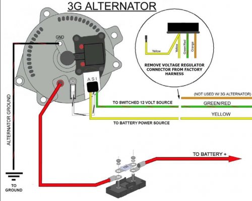
Is it my alternator?

RSchanz

Full Access Member
Joined
Sep 29, 2020
Posts
303
Reaction score
94
Location
Petaluma, CA
Lately it seems like if I have a problem it's got to be electrical related.

Truck wouldn't start the other day. I haven't been using it that much lately so I figured there must be some kind of short draining the batteries. Charged the batteries back up but it seemed like they wouldnt get much higher than 12v. I started the truck anyways and realized that the volts wouldn't increase when accelerating. Seems like they barely want to get above like 12.2v (maybe damaged from alternator?). With the multimeter I tested positive lead to positive terminal on the alternator and negative lead to negative terminal on the battery and got like 8v. It was hard to get a consistent reading there. Does this mean the alternator is shot? I assume so but wanted to know if there was anything else I could check before removing it.

I should probably note that I replaced the voltage regulator about 7 months ago because I found that the old one was stuck switched "on" and drained my batteries flat.
 

DaveBen

Supporting Member
Supporting Member
Joined
Sep 29, 2010
Posts
1,928
Reaction score
645
Location
Ukiah, Ca
What is the voltage at the Battery when charging form the alternator? It should be around 12.6 or more. This will show the alternator is charging. If the voltage is less, then the alternator is bad.
 

RSchanz

Full Access Member
Joined
Sep 29, 2020
Posts
303
Reaction score
94
Location
Petaluma, CA
What is the voltage at the Battery when charging form the alternator? It should be around 12.6 or more. This will show the alternator is charging. If the voltage is less, then the alternator is bad.

Yeah when truck is on it doesn't increase above 12.2v and when accelerating it doesn't jump either.
 

Ohiogoldfever

Registered User
Joined
Apr 20, 2024
Posts
15
Reaction score
9
Location
Ohio
Yeah when truck is on it doesn't increase above 12.2v and when accelerating it doesn't jump either.

Sounds like a bad alt to me. I’d check all your connections and jazz first. Doesn’t take much shmuu to create a lack of connection. I’d be willing to bet more than one Starter has been replaced over a bad connection when the fella was sure it was a bad starter. Same applies with the alt. Any high amperage connection can get burnt and the oxide created makes things wonky.
 

BeastMaster

Full Access Member
Joined
Feb 7, 2017
Posts
344
Reaction score
291
Location
Orange, California
I thought you put that to bed.

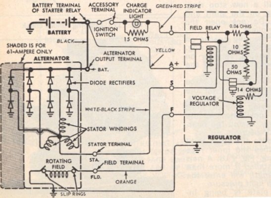
Given what I see right now, I'm in Nero's camp. I found a wiring diagram for a 1G alternator as per Cubie's post.

This alternator has a ground circuit, a big ( probably 6 gauge or so ) wire that feeds the positive battery bus, likely through a fusible link, and two smaller wires that go to the voltage regulator , marked "S" and "F".

"S" would be the Stator sample. It's one leg of the 3-phase alternator raw AC output. The Voltage Regulator looks at this so it can tell if the alternator is spinning, so it won't engage field current if the alternator isn't spinning.

"F" is the Field control line. Controlling current into this line will control how much output current is desired from the alternator.

Disconnect "F" at the alternator. Provide an alternate path via a clip wire to provide current into the alternator's "F" connector.

The Voltage regulator is no longer in control. It's disconnected. You don't want to brute force the output of the voltage regulator.

So now you control the alternator directly through feeding the alternator directly via it's control line. Monitor your battery voltage as you have been doing. Start the engine. You should have no alternator output.

Briefly touch your control wire to the positive battery terminal to provide current into the alternator field to create it's magnetic field, which will now induce the Stator windings to start producing current from the rotating rotor's magnetic field.

You should see a spark as the field electromagnet winding begins drawing current, while the alternator output goes to fullbore output current. You might even hear your engine slow a bit as the alternator loads the engine. If you start charging like mad now, your alternator is probably ok...something is wrong in the voltage regulator circuit.

If nothing happened, try shorting the wire connected to alternator "F" to ground instead of the positive battery terminal. It's not really clear to me from my reading of the wiring diagram whether I must force current into the "F" alternator connector, or sink current from the "F" connector to establish the field.

No matter which way, the rotor is just an electromagnetic coil fed through brushed slip rings, and a try will either work or it won't.

Looking at the wiring as shown, it looks to me that the regulator will feed current from "I" to "F" when "S" tells the regulator that the rotor is spinning and the battery voltage sample presented at "A" indicates the battery needs charging.

These are what I found and believe this is likely what you have...


You must be registered for see images attach


This test should work regardless of whether the Stator "S" wire is connected or not. Just don't force the battery current directly into the alternator on the S connector. It's an alternator output and won't like having current rammed into it or having it shorted to ground.

Let me know what you find.

I am entertaining the idea you *might* have some shorted turns on one of the windings in your alternator, which would increase the field current required to generate design charging current... Such increase of field current overloading the field drive circuit of the voltage regulator hence shortening it's life. However I am also quite aware that a lot of new parts are not as robust as the older parts. I am currently experiencing some of this personally with my engine tach sensor confusing my E4OD transmission controller. . However, alternator's are expensive and I would be loathe to advise change out until this is verified.

Ooooh, I hate spending money replacing perfectly good parts.

Note:. I have made numerous edits to this as I often consider what I wrote and it could have been better. If I'm gonna do something, do it right.
 
Last edited:

RSchanz

Full Access Member
Joined
Sep 29, 2020
Posts
303
Reaction score
94
Location
Petaluma, CA
I thought you put that to bed.
I wish it worked, haha. I went back and read the thread and it seemed like even after I replaced the voltage regulator the charging still wasn't very strong so I'm thinking that you're right in the fact that the alternator has shorted turns and is damaging the voltage regulator.

I'm going to go under the hood and try to trace these wires and also plug the trickle charger back in so the batteries can get back up to where they should be so I can test (currently at 11.8v). For the control wire it can just be any similar gauge wire (probably 12 or maybe 10?) that has exposed metal wire on either end and doesn't need to have a clip right? And I'm under the assumption that some shoddy wiring has happened in the past on here so I want to be safe. If I'm holding my test wire bare handed but touching the insulation not exposed wire I should be fine right? Not sure I want the force of 2 12v car batteries zapping me.
 

BeastMaster

Full Access Member
Joined
Feb 7, 2017
Posts
344
Reaction score
291
Location
Orange, California
I'd still be a little careful regarding the wiring around an alternator and potential electric shock. Alternators are highly inductive and can deliver surprisingly nasty voltage spikes upon any rapid current changes.

This phenomena, commonly called "inductive kickback" is the electrical analog of the "water hammer" that vexes plumbers.

Have you noted your alternator running unusually hot for no apparent reason? Shorted windings make an alternator or transformer run quite hot.

Anyway, see if you can get it to put out. Max field current should be around 10 amps or so to command 100 amps out. Don't wanna do this for more than a few seconds... alternator's just not built to run this way for long.

Yeh, plain old 12 gauge wire oughta do it. A Hank of whatever is handy. Some sort of clip would probably be handy at the alternator just to hold the wire on the correct terminal, while personally I would use a small stripped area at the other end as I intend to only briefly touch it to the positive battery pole ( or ground ) while watching the reaction to my doing so. Like, do the headlights brighten when I goose the field current? What voltage shows up at the battery?

I leave a file you may find useful.
 

Attachments

  • Alternator_Automotive-2016.pdf
    125.7 KB · Views: 3
Last edited:

RSchanz

Full Access Member
Joined
Sep 29, 2020
Posts
303
Reaction score
94
Location
Petaluma, CA
Thanks for the above. Headed out of town this weekend and jumping into this next week. Will report back!
 
Top