A/C comp for my super sucker.. What are all the wires for?

EMD_DRIVER

Say what?!?!
Joined
Jun 3, 2008
Posts
1,807
Reaction score
3
Location
Beaufort, SC
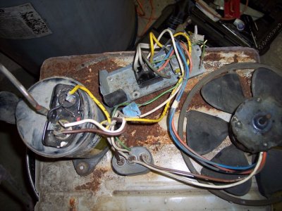
I picked up an old A/C, that has been laying along the railroad tracks for about 3 years. I've seen it sitting there every day and figured it might be useful to draw a vacuum.

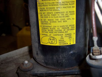
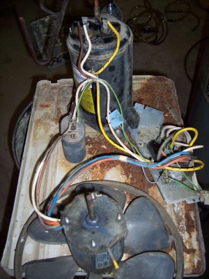
I pulled it apart and kept the base, compressor and the fan. I've left all the wires connected, since I have no idea what does what. I'll post a reply with pictures, and would like anyone that knows anything about them to let me know what to trash and what to hook up. I'd also like to know which two wires would allow me to wire the fan up to 120VAC. I want to mount it somewhere in the garage, to cool me off while I'm "Working" ;Sweet

Gary
 

DGT

Full Access Member
Joined
May 16, 2008
Posts
60
Reaction score
1
Location
texas
Is it a 120 unit or 230 ? Some fans have dif speeds. On fan make sure to wire only common wire and one speed. If you wire two speed wires you will burn up motor.If extra speed wire touches ground you will burn up motor.If you over amp motor it will not last as long. Sometimes you have to close of some air to motor to reduce amps because they are made to have some resistance to air flow. Find rated amps on motor some where then use clamp on amp gauge to check if amps are to high if so blank of some air to blower.

Compressors only pump vapor. Hase 3 wires common / run / start .
Needs the capacitor to work. common goes to L1 run goes to L2 and common of the capacitor start goes to herm on capacitor. Compresors are made to run with no mosture in a hermaticly closed system so if it works will only pump air for short time and will blow most of its oil out the discharge line.
The oil cerculates in system and is returned to compressor threw the suction line. A good piston compressor will pull a vacume to say 14 in hl.
 

EMD_DRIVER

Say what?!?!
Joined
Jun 3, 2008
Posts
1,807
Reaction score
3
Location
Beaufort, SC
Here are the three pics.. One of the whole setup, one of the label on the compressor and another view of the whole setup.

Gary
 

Attachments

  • comp1.jpg
    comp1.jpg
    158.1 KB · Views: 7
  • comp2.jpg
    comp2.jpg
    118.3 KB · Views: 6
  • comp3.jpg
    comp3.jpg
    150.1 KB · Views: 6

DGT

Full Access Member
Joined
May 16, 2008
Posts
60
Reaction score
1
Location
texas
Looks like common on capacitor is the center terminal whitch is white wires
this is netral on 120 v . Looks like 2 speed fan blue and yellow this will be
120 hot on one cap off the other wire. White to compresor is also netral on120 or run to compresor. Black should be 120 v hot common on compresor.The other wire on compresor is start should go to herm on capacitor.That setup has a single dual capacitor to run both compresor and fan.To split them you will need another capacitor.See if they both work first.
Also that is a rotory compresor. Get a cord put white wire to center termanal
of capacitor then 120 v hot to black on compresor and one speed wire to
fan and plug into 120 v outlet see if they run.
 
Top