Thanks, I've read about turning up fuel but wasn't sure. What is it doing in the IP pushing something farther open that gives more fuel?
Jim
Adjusting the fuel screw spreads the C ring which pushes two rollers out that in turn increases the circular motion of a cam that rides on the rollers, the cam increases the stroke of the plungers that delivers the fuel at a high pressure (5000+ PSI) to the injectors.
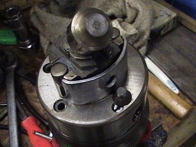
Heres a pic of the C ring and rollers. The shaft was sheared on this particular IP because the adjustment was too much.
.
Injection pump operation
The DB2 is an opposed-plunger, inlet-metering, distributor-type diesel injection pump. It was designed for low-cost production and mechanical simplicity. A typical DB2 (there were slight variations on the design for different engines) has a total of approximately 100 components and only four main rotating members. There are no spring-loaded components, none are lap-fitted in manufacture, and there are no ball bearings or gears. The pump has a single pumping chamber in which two opposed plungers are actuated by an internal cam ring.
Fuel is drawn from the fuel tank by a mechanical lift pump that works independently of the DB2 injection pump; it passes through two filters and then into the injection pump inlet. From there, fuel flows past the inlet filter screen to the vane-operated transfer pump contained in the pump end cap. The vane-type transfer pump consists of a stationary liner and spring-loaded blades carried in slots at the rear of the transfer pump rotor. As the blades rotate in the liner, they move outward and the volume increases until the leading blade passes out of registry with the inlet slot. The fuel between the blade is carried to the bottom of the transfer pump liner and enters the outlet groove. As a result, pressurized fuel is delivered through the pump into a channel to the hydraulic head passage.
Fuel delivered to the head passage under transfer pump pressure splits in several directions. A portion of the fuel goes to the pressure side of the pressure regulator. The remainder enters a circular passage in the head from which radial passages lead to the vent wire assembly and then to the governor housing and housing pressure regulator; the transfer pressure tap hole plug, which was used for test-stand purposes only; the advance mechanism, and the metering valve.
The pressure regulator assembly in the transfer pump regulates fuel volume based on changes in pump speed--pressure increases with pump speed.
The vent wire assembly is located behind the metering valve bore, and is made up of a J-shaped wire retained in a hollow screw. The wire is free to vibrate and restrict excessive return oil and undue pressure loss.
Fuel entering the housing from the vent fills the housing, lubricates the internal components and cools and carries away any small air bubbles through the return oil line.
The housing pressure regulator is a ballcheck fitting in the governor cover that maintains even housing pressure, except when the housing pressure cold advance solenoid is operating, and allows fuel to return to the fuel tank.
The advance system is a simple, direct-acting hydraulic mechanism. Powered by fuel pressure from the transfer pump, the advance mechanism moves the power piston to rotate the cam to vary the delivery timing. It advances or retards the start of fuel delivery in response to engine speed changes. The advance piston, located in a bore in the housing, engages the cam advance screw and so moves the cam in the direction opposite of rotor rotation. When engine speed decreases, hydraulic pressure is reduced and the cam is retarded because of low transfer pressure. When engine speed increases, transfer pump pressure increases and moves the advance piston and cam.
In addition to the normal speed advance, a mechanical light-load advance is furnished as a function of throttle angle. It consists of a face cam attached to the throttle lever and an external pivot lever. The mechanical light-load advance provides proper advance for light loads when transfer pressure is low and the cam ring is in retard, by changing the reference point of the servo valve.
1981 and later models were also equipped with a housing pressure cold advance solenoid. This consisted of a solenoid assembly in the governor cover, and a ballcheck fitting. The unit allowed more advance at cranking and engine warm-up by reducing housing pressure, which allowed the power piston to move farther (approximately three degrees) in the advance direction. This resulted in a slower, more complete burning of the fuel.
The min-max governor regulates the injection pump at low idle and maximum rated speeds. At speeds between these two ranges, the throttle lever and governor spring of the governor directly control the metering valve.
The governor assembly consists of a cage with flyweights mounted on the rotor and a system of linkages. The movement of the weights acting against the governor thrust sleeve rotates the metering valve by means of the governor arm and linkage hook. The amount of rotation varies the position of the metering valve, thus controlling the amount of fuel to the pumping plunger. The governor derives its energy from the weights pivoting in the weight retainer. Centrifugal force throws the weights outward, moving the thrust sleeve against the governor arm, and rotates the metering valve through a simple positive linkage.
Retention of heat is a critical factor in fuel thinning after a high ambient heat soak. As the hotter, thinner fuel passes through the pump, internal leakage increases, reducing fuel output. To compensate for this loss, a bimetallic temperature compensator strip was added to the governor arm to increase metering valve opening. This provided a compensated idle speed curve and corrected engine idle speed at elevated ambient temperatures.
The metering valve allows a varying amount of fuel to pass through the charging passage to fill the pumping plungers in the distributor rotor. As the rotor revolves, the inlet passage registers with the charging ports in the hydraulic head, allowing fuel to flow into the pumping plunger. With further rotation, the inlet passages move out of registration and the discharge port of the rotor registers with another of the head outlets. While the discharge port is open, the rollers contact the cam lobes and force the plungers together. Fuel trapped between the plungers is then pressurized and delivered through the delivery valve and the nozzle (injector) to the combustion chamber.