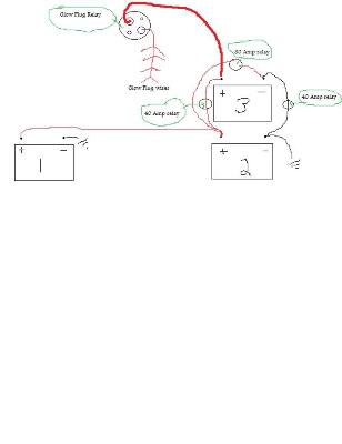
Don't mind the crappy diagram, I think it still gets the point across. I did it in CAD first, but I don't think everyone has CAD to open the attatchment.
I think everyone has paint.
79592[/ATTACH]"]
You must be registered for see images attach
The bottom 2 batteries are stock configuration. The third battery has been in the truck for quite some time now and I had it hooked up to a relay anyway, so I didn't need to buy one.
The thick red wire is the 8ga wire that runs directly to the GP relay. I took off the constant 12V wire, and also disconnected it from the starter relay. Its the black one with orange stripe on it. The only wire on that terminal is the 24V wire. The only wire that is on the other side is the glow plugs. I took off the other 2 wires.
The second battery connects in parallel to the third battery, positive to positive, and negative to negative. Both of those connecting wires are 8ga, and both are interrupted to the 40 amp relays. Both relays are connected together to a switch in the dash, and grounded together, either to the second battery or to a chassis ground. NOT to the third battery or you won't be able to turn off the 24V. We'll call this switch 1.
The second battery also has a positive lead coming off it, and going to a 80 amp relay. The other post on the relay is going to the ground on the third battery. This makes the positive terminal on the third battery see 24V. That relay is also switched and located in my dash. Call this switch 2.
That's it from what I can tell. When you start the truck up in the morning, you are going to have switch 1 off, and switch 2 on. You glow the plugs with the manual button to a time of your choosing, and crank the engine. The truck will run on this setup, but it wont charge the third battery. You must then turn off switch 2 FIRST, and then turn on switch 1 which connects the batteries in parallel and all 3 are now charging. When you shut off the truck make sure all switches are off, and NEVER have both switches on at the same time or you'll be looking for new relays (I think, if not worse). Oh yeah, and if you don't have switch 2 on when you glow the plugs, you'll only be giving them 12V, switch 2 must be on for 24V.
This can be done with just 2 batteries, but I had 3 already so I utilized them. I would assume the same will work for a 2 battery system by just taking away battery 1 from the schematic.
The stock GP relay and GP wires are strong enough to withstand the 24V for atleast 2 minutes, as that is how long I've tested them.
Complete parts list:
2, 4-post 40 amp relays, slide connector type.
1, 4 post 80 amp relay, stud type.
10' of 8ga wire.
20' 18ga wire. (I already had the switches ran so I just put the wires to the relays, so I didn't buy this wire)
8ga female slide connectors
18ga female slide connectors
8ga copper lugs along with new battery terminals for multiple connections to the same terminal.
Switches of your choosing.