Whats wrong with this GP setup?

oworm

Full Access Member
Joined
Nov 13, 2010
Posts
142
Reaction score
0
Location
Indianapolis IN
Whats wrong with this GP setup?
 

Attachments

  • IMG_0913.jpg
    IMG_0913.jpg
    572.9 KB · Views: 35
  • IMG_0912.jpg
    IMG_0912.jpg
    555.9 KB · Views: 28

rhkcommander

Full Access Member
Joined
Feb 9, 2010
Posts
2,603
Reaction score
90
Location
Oregon
Looks like your trying to do manual setup,

Use the ground ran to a switch to initiate the relay. Leave it on the ground connector. Wire the 12v batt side to the signal stud looks like you did. Then the other big stud goes to the glow plugs.

If that is how you have it setup and you still have problems, does the relay work? No: get new relay; You'll hear it click on when you turn it on and click off when ya tell it. If yes, clean any corrosion, check the wiring harness to the plugs. Nearby is a spot that likes to melt and eventually short.

A volt meter or continuity tester can come in handy here too
 

oworm

Full Access Member
Joined
Nov 13, 2010
Posts
142
Reaction score
0
Location
Indianapolis IN
Looks like your trying to do manual setup,

Use the ground ran to a switch to initiate the relay. Leave it on the ground connector. Wire the 12v batt side to the signal stud looks like you did. Then the other big stud goes to the glow plugs.

If that is how you have it setup and you still have problems, does the relay work? No: get new relay; You'll hear it click on when you turn it on and click off when ya tell it. If yes, clean any corrosion, check the wiring harness to the plugs. Nearby is a spot that likes to melt and eventually short.

A volt meter or continuity tester can come in handy here too

The relay is new. The two bullet connectors are disconnected until I know where they should go. I'm not sure about how the rest is setup
 

smolkin

Stuck inside Mobile
Joined
Mar 5, 2009
Posts
677
Reaction score
2
Location
Mobile, AL
The bullet connectors are for the WTS light and signal from the gp controller, respectively. Neither one is really necessary in a manual gp setup.
 

OLDBULL8

Good Morning Ya'll.
Supporting Member
Joined
Feb 12, 2009
Posts
9,923
Reaction score
338
Location
Delphos , Ohio
Can you explain it to me? The wires in your pic don't seem to correspond to my setup, either in color or placement

Nope! Looks like some African engineering has been done to your wiring. You just have to figure out where the existing wires should go from the noted connections in the picture.

EDIT: Looking at your pic again, you don't have a GP controller, just a relay. From that it's impossible to guide you where the wires shown are supposed to go.
 
Last edited:

Diesel JD

Full Access Member
Joined
Feb 7, 2006
Posts
6,148
Reaction score
7
Location
Gainesville, FL
That's because the controller Oldbull88 posted is the 87 and later solid state connector. You have the 83-86 latching relay with the controller screwed into the head. I can't tell you where things are supposed to be on the 83-86 relay because I was so scared of that thing failing I tossed it soon after I got the truck. First I ran manual glow plugs and once I got all the other issues my inexperience had caused out of the way it worked superbly, then because I occasionally lend the truck out and have others work on it also, I converted to the 87+ system Oldbull posted which also has worked superbly well. Listen to these other guys; the older system is meant for a manual conversion, but don't glow your plugs more than 8 seconds or so unless you have converted to a dual coil self limiting style plug or a 12 volt rated plug such as the ones used in the "slow glow" early 5.7 Oldsmobile diesels.
 

oworm

Full Access Member
Joined
Nov 13, 2010
Posts
142
Reaction score
0
Location
Indianapolis IN
That's because the controller Oldbull88 posted is the 87 and later solid state connector. You have the 83-86 latching relay with the controller screwed into the head. I can't tell you where things are supposed to be on the 83-86 relay because I was so scared of that thing failing I tossed it soon after I got the truck. First I ran manual glow plugs and once I got all the other issues my inexperience had caused out of the way it worked superbly, then because I occasionally lend the truck out and have others work on it also, I converted to the 87+ system Oldbull posted which also has worked superbly well. Listen to these other guys; the older system is meant for a manual conversion, but don't glow your plugs more than 8 seconds or so unless you have converted to a dual coil self limiting style plug or a 12 volt rated plug such as the ones used in the "slow glow" early 5.7 Oldsmobile diesels.
Actually there is no controller in the head. This is a reman 6.9. The controller port is plugged off. The old controller in the previous engine didn't work and the PO wired it for manual GP's anyway.
 

Diesel JD

Full Access Member
Joined
Feb 7, 2006
Posts
6,148
Reaction score
7
Location
Gainesville, FL
Doesn't matter....it's the same system, and he did you a favor by tossing that troublesome piece of crap. Failure mode is it sticks on and roasts your glow plugs. At least with a manual controller only you can kill them; with the later style controller failure mode is it just doesn't work.
 

OLDBULL8

Good Morning Ya'll.
Supporting Member
Joined
Feb 12, 2009
Posts
9,923
Reaction score
338
Location
Delphos , Ohio
Maybe this will help.

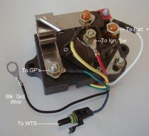
The large terminal with the white wire jumper and black wire should go to the battery positive, the other large terminal wires should go to the glow plugs, the small terminal with the black wire on it should go to a momentary contact push button terminal, and the other side of that push button should go to ground. For the WTS lite if you have one, the positive wire to it should come from the large terminal with the three wires, and the ground wire to the WTS can come from the small terminal with the black wire on it or at the push button. The WTS lite will lite showing the relay is energized only for how long you hold the push button on. That's my best guess, as far as the other wires shown with the 90* bullet connectors, you will have to trace them out to see where they go.
 

Attachments

  • relay.jpg
    relay.jpg
    555.9 KB · Views: 12

Matrix37495

The Amish Wolfman
Joined
Nov 6, 2010
Posts
1,228
Reaction score
6
Location
Terre Haute, IN
Old bull, if thats the same solenoid i have (looks like it is) then it grouns through the base. By having him connect the B+ to the "S" terminal it would never turn off....Bad news for the glow plugs...
 

oworm

Full Access Member
Joined
Nov 13, 2010
Posts
142
Reaction score
0
Location
Indianapolis IN
When I press the manual button in the cab there is no click like there was before. This is a new relay so it must be working. What is worrying me is that loop wire going from the Battery to the S terminal. Should that even be there?
 

Latest posts

Forum statistics

Threads
91,310
Posts
1,130,116
Members
24,118
Latest member
Grizzly Wrecker
Top