Slow crank after possible overheat

XOLATEM

Full Access Member
Joined
May 5, 2023
Posts
614
Reaction score
796
Location
Virginia... in the brambles
KOEO Output state self test finds p0198 (oil temp sensor circuit high), p0380 (glow plug circuit), p0603 (batteries disconnected), p0470 (exhaust back pressure circuit malfunction).
We know that the batteries were disconnected...but my question is...

Do these other codes have anything in common...?

Do we have a wiring diagram on this system..?

Do we have tunnel vision on one thing when we should be looking at it from another angle...?


why my ICP signal reading would climb like that.

So...what component would relieve the pressure...? Isn't there a regulator actuator in the system..?

I went to a couple of classes on this one...but...I never used it and my books are sealed up and put away from the 'moving event'...

If it were me...I would record the codes...clear the codes...and try to start it...and then scan the codes again...if a circuit failure code comes back...hit those first...
 
Last edited:

Luke_IDI

Registered User
Joined
Mar 8, 2022
Posts
77
Reaction score
8
Location
New Orleans
It’s possibly there is an electrical basis for all of this. Which indeed I will look for.
We know that the batteries were disconnected...but my question is...

Do these other codes have anything in common...?

Do we have a wiring diagram on this system..?

Do we have tunnel vision on one thing when we should be looking at it from another angle...?


So...what component would relieve the pressure...? Isn't there a regulator actuator in the system..?

I went to a couple of classes on this one...but...I never used it and my books are sealed up and put away from the 'moving event'...

If it were me...I would record the codes...clear the codes...and try to start it...and then scan the codes again...if a circuit failure code comes back...hit those first...
Basically, I first want to verify if there is enough actual ICP to fire the injectors. The ICP is really only at the top of my mind insofar as it monitors whether there is enough oil pressure to fire. Aside from that, it is secondary as the truck should run without it. Once I verify there is enough actual ICP, I will move onto supposed electrical issues. But there is no point troubleshooting electrical issues that might not exist without knowing for sure that there is enough ICP to fire the injectors.

There is a regulator, the ICR, which diverts oil pressure to bring pressure down to desired level. However, is being commanded by the PCM to give maximum pressure to the rail. So why is the the case? Why does the ICR duty cycle not decrease if the computer really is seeing high ICP?

I am gathering gauges and fittings now to test ICP mechanically. Will report back asap. This should give a definitive answer to the question posed in my ICP thread.
 

Rdnck84_03

Full Access Member
Joined
Jan 15, 2019
Posts
1,126
Reaction score
1,209
Location
Kansas
Did you happen to look and see what % duty cycle the pcm was commanding from the IPR with the ICP unplugged?

I feel like I saw where you posted the year of this vehicle, but I just scanned all the way back through and I can't find it. If you get to a point that you need good wiring diagrams I have all of the good Mitchell's diagrams for a 97 f350 and an 01 f350 so I should be able to hook you up on the obs and superduty engine harness.

James
 

Luke_IDI

Registered User
Joined
Mar 8, 2022
Posts
77
Reaction score
8
Location
New Orleans
Did you happen to look and see what % duty cycle the pcm was commanding from the IPR with the ICP unplugged?

I feel like I saw where you posted the year of this vehicle, but I just scanned all the way back through and I can't find it. If you get to a point that you need good wiring diagrams I have all of the good Mitchell's diagrams for a 97 f350 and an 01 f350 so I should be able to hook you up on the obs and superduty engine harness.

James
I did not happen to look at duty cycle with ICP unplugged. Will check that and post next time I am at the truck.

It’s a 2003 E-450. I found some good wiring diagrams from a 2002 F-350 as a sticky on the Powerstroke.org forum. I do appreciate the offer and will let you know if needed!
 

Luke_IDI

Registered User
Joined
Mar 8, 2022
Posts
77
Reaction score
8
Location
New Orleans
Ok, finally managed to assemble a few different adapters, a grease whip, and a 3000 psi gauge to look at ICP manually.

The ICP sensor thread is M12x1.50. The seal is with an O Ring as with the sensor. My local hydraulic shop had this fitting to JIC, then JIC to 3/8” pipe, 3/8” pipe to 1/8” pipe, grease whip (rated 3000 psi), 1/8” pipe to 1/4” pipe, gauge.

As verified by the mechanical gauge, ICP does indeed rise to 3000 psi in a matter of a couple of seconds. So to answer the first part of my original question, the ICP is reading correctly.

Next question: why is the PCM commanding full IPR duty cycle if there is plenty of pressure to fire the injectors?
 

Luke_IDI

Registered User
Joined
Mar 8, 2022
Posts
77
Reaction score
8
Location
New Orleans
Fuel pressure at the fuel bowl 64 psi. Drops maybe 2-4 psi when cranking. Drained fuel from fuel bowl. Smells and feels like diesel. It’s not black.

We have good ICP and a proper reading. We have decent fuel pressure. We have RPM signal.

Someone on the other thread suggested IDM is not sending enough voltage to fire the injectors. Hmm. Maybe I will pursue this path a bit by hooking up a scope to an injector connector.
 

Luke_IDI

Registered User
Joined
Mar 8, 2022
Posts
77
Reaction score
8
Location
New Orleans
Fuel looked ok-ish, but there was a good amount of rusty stuff in it. I am not sure if this came from the tank or from the little metal tube that runs down from the fuel bowl drain.
 

Attachments

  • D5CB7BF2-7748-40D7-9F68-41799B21E651.jpeg
    D5CB7BF2-7748-40D7-9F68-41799B21E651.jpeg
    208.5 KB · Views: 4
  • ED289676-BDF5-4D79-BD8D-A8AEB76AEC70.jpeg
    ED289676-BDF5-4D79-BD8D-A8AEB76AEC70.jpeg
    176.1 KB · Views: 4

greenskeeper

Full Access Member
Joined
Mar 16, 2013
Posts
995
Reaction score
202
Location
PA
About how much oil should I see coming out of the injectors while cranking?
sorry for the delay, there should be oil coming from all of the injector spouts... no oil indicates the injector isn't firing... it isn't a lot of oil but should be easily visible dripping off the spout onto the head.
 

greenskeeper

Full Access Member
Joined
Mar 16, 2013
Posts
995
Reaction score
202
Location
PA
Ok, back at the truck. Hooked up FORScan and have obtained some ICP and IPR % readings. Cranking, IPR % goes to approximately 60%. ICP builds steadily over a few seconds, maxing out around 26,000 kPa, equal to about 3700 psi. This seems like plenty enough to fire, in fact it seems excessive. I am not seeing oil coming out of the injectors while cranking, however. Could an IPR valve stuck open (supplying maximum ICP) cause this?

Mechanical gauge shows you've got plenty of psi to fire the injectors...so....

If you have no oil coming from any of the injector spouts while cranking that would point in the direction of the electrical side of the injectors... IDM, etc.

Can you run a buzz test with your scanner? No buzz means electrical side of the injectors has a fault.

Do you get the WTS light when turning the key to "on" ?
 

Luke_IDI

Registered User
Joined
Mar 8, 2022
Posts
77
Reaction score
8
Location
New Orleans
Mechanical gauge shows you've got plenty of psi to fire the injectors...so....
If you have no oil coming from any of the injector spouts while cranking that would point in the direction of the electrical side of the injectors... IDM, etc.

Can you run a buzz test with your scanner? No buzz means electrical side of the injectors has a fault.

Do you get the WTS light when turning the key to "on" ?
WTS light comes on just for a second. I believe there is an oil temp fault possibly messing with the glow plug system.

There is an electrical pulse to the injector. I thought the wave form looked a little sketchy, so it was checked against a known good IDM today. Wave form with the new IDM attached, where each vertical square is 20v. Still no fire. I still cannot make out this oil from the injectors everyone talks about. Wish I had a video showing the oil spouting to look at. Everything else seems good here. Is it possible the PCM is giving a sort of bad command signal to the IDM, resulting in incomplete injector pulse?

I view of the data I am really starting to scratch my head. So I am next doing to revisit the question of compression. It has a good strong crank and sounds like it has even compression. We put a cheap Harbor Freight compression tester on it today, but the check valve in the tester wouldn’t hold. That being said, we saw spikes of 200 psi with no check valve installed and a held reading of maybe a little over 100 psi. Which does not bode at all well. But I think a better test is necessary, given that there are no audible signs of low compression.
 

Attachments

  • 966F0320-D7AC-4DBE-B544-D76475656ACC.jpeg
    966F0320-D7AC-4DBE-B544-D76475656ACC.jpeg
    240.3 KB · Views: 5

greenskeeper

Full Access Member
Joined
Mar 16, 2013
Posts
995
Reaction score
202
Location
PA
Mechanical gauge shows you've got plenty of psi to fire the injectors...so....

WTS light comes on just for a second. I believe there is an oil temp fault possibly messing with the glow plug system.

There is an electrical pulse to the injector. I thought the wave form looked a little sketchy, so it was checked against a known good IDM today. Wave form with the new IDM attached, where each vertical square is 20v. Still no fire. I still cannot make out this oil from the injectors everyone talks about. Wish I had a video showing the oil spouting to look at. Everything else seems good here. Is it possible the PCM is giving a sort of bad command signal to the IDM, resulting in incomplete injector pulse?

I view of the data I am really starting to scratch my head. So I am next doing to revisit the question of compression. It has a good strong crank and sounds like it has even compression. We put a cheap Harbor Freight compression tester on it today, but the check valve in the tester wouldn’t hold. That being said, we saw spikes of 200 psi with no check valve installed and a held reading of maybe a little over 100 psi. Which does not bode at all well. But I think a better test is necessary, given that there are no audible signs of low compression.
WTS light will come on for a split second if ambient temps are high, longer as ambient temp decreases although it has no direct correlation to how long the glow plugs are powered.

IDM voltage should be 115 volts DC

Here is a video I found of the oil spouts.. you can see the oil flowing at idle coming out of the spout next the the pushrod.

Remember this is at idle, so just cranking it won't be quite as much but everytime the injector fires it should drip oil from the spout. Also any oil coming from any other part of the injector besides the spout would be a problem.

xc_hide_links_from_guests_guests_error_hide_media
 

Luke_IDI

Registered User
Joined
Mar 8, 2022
Posts
77
Reaction score
8
Location
New Orleans
WTS light will come on for a split second if ambient temps are high, longer as ambient temp decreases although it has no direct correlation to how long the glow plugs are powered.

IDM voltage should be 115 volts DC

Here is a video I found of the oil spouts.. you can see the oil flowing at idle coming out of the spout next the the pushrod.

Remember this is at idle, so just cranking it won't be quite as much but everytime the injector fires it should drip oil from the spout. Also any oil coming from any other part of the injector besides the spout would be a problem.

xc_hide_links_from_guests_guests_error_hide_media
Thanks, that video is a huge help. I think I will be able to get a good look at the spouts next time we crank it.
 

Luke_IDI

Registered User
Joined
Mar 8, 2022
Posts
77
Reaction score
8
Location
New Orleans
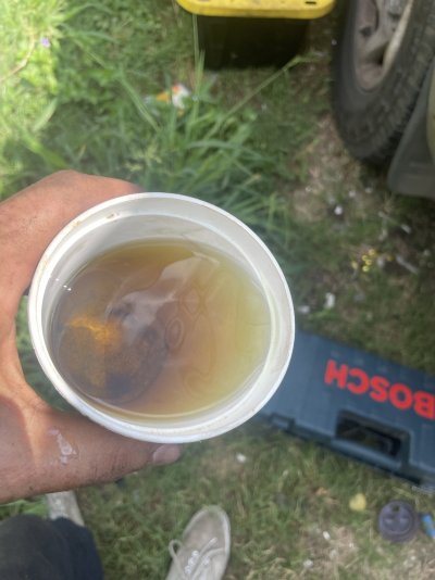
I did another compression test today. Pulled all glow plugs (except for one which is bent over, not allowing the socket to slip onto it. I have no idea how it might have gotten this way). I am using a Harbor Freight compression tester as a base. I have a M10x1.0 ORB fitting, 18” grease whip, quick connect with Schrader valve, and a 0-600 psi gauge. I did not trust the HF gauge as it leaked out all of the glycerin and besides, the needle seemed to stick when cranking. So I replaced the gauge with one from a nearby hydraulic supply shop. It seems to be of better quality, though I have not tested it against another gauge.

The compression tester holds pressure. There is some question of whether a long hose upstream of the Schrader valve will lower compression numbers. It seems the proper way to account for this would be to add the extra volume of the hose to the full cylinder volume and to the compressed cylinder volume and compare the resulting compression ratio to that of the cylinder without the hose. This ratio should give the amount of apparent loss in compression due to the addition of the hose. Assuming a 1/8” diameter by 18” hose, I calculate the volume of the hose to be about .221 cu in. The engine is 444 cu in, 55.5 to a cylinder. Dividing by 17.5:1 compression ratio gives 3.171 cu in volume at TDC. New cylinder volumes at BDC and TDC respectively would be 55.721 cu in and 3.392 cu in. The resulting compression ratio including the volume of the hose would then be approximately 16.43:1. By this logic, my apparent compression readings should equal approximately 94% of the actual compression produced. I felt I needed to go through these calculations to attempt to confirm the accuracy of my compression numbers, which as you may have guessed, are low:

1: 220
2: 180
3: (not tested - bent glow plug)
4: 170
5: 200
6: 200
7: 200
8: 140

What surprises me is that, with the exception of cylinder 8, all cylinders are with 25% of each other. Regardless, I want to make sure to verify the results produced by my setup against something else known. I hope to plug what I have (minus the adapter) into my truck’s gas engine and compare against my gas compression tester to definitively verify these results.

Low compression of this magnitude would certainly explain why everything else seems to check out, but the engine just won’t fire. I am still hesitant to say the engine was severely overheated, as the driver says he managed to shut the engine off very shortly after the temperature warning light came on. I saw a mention of loose injector hold-down bolts causing low compression. Are there any common reasons for low compression in an otherwise healthy engine?
 

Luke_IDI

Registered User
Joined
Mar 8, 2022
Posts
77
Reaction score
8
Location
New Orleans
Upon examining my gauge setup, the quick connect fitting was not fitting snugly and was leaking. Test to be repeated with new quick connect and check valve.
 

Forum statistics

Threads
91,284
Posts
1,129,796
Members
24,099
Latest member
IDIBronco86

Members online

Top