All I can come up with for the moment. Hope it helps.
Fuel System
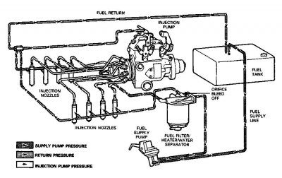
Fuel from the tank is routed to the fuel supply pump through a combination fuel filter, heater and water separator. The filter header contains a continuous vent (orifice bleed- off system) which aids starting by eliminating the need to manually prime the fuel filter. A vacuum switch is incorporated into the fuel filter header which will activate an instrument panel lamp, indicating the need for filter replacement. The water separator portion of the filter assembly has a probe which activates an instrument panel lamp when the filter requires draining at the water and sediment drain (located on the bottom of the assembly).
NOTE:
Proper filtration of diesel fuel cannot be overemphasized. It is essential for long component life and reliability.
Fuel enters the inlet of the injection pump and is delivered under high pressure through injection nozzles into the engine cylinders for combustion. Each nozzle incorporates a fuel return fitting that returns excess fuel to the fuel tank. Excess fuel from the injection pump and each injection nozzle is collected in bleed-off lines and returned to the fuel tank.
Injection nozzles are located on the inboard side of the cylinder head. This configuration provides better access to the engine for servicing.
The fuel shutoff solenoid controls the flow of fuel into the injection pump charging circuit (high pressure). With the ignition switch in START or RUN, the solenoid is energized and fuel is allowed to flow to the injection pump charging circuit. With the ignition switch off, fuel flow to the injection pump charging circuit stops.
Injection Pump
The diesel fuel injection pump accurately meters and delivers fuel to a nozzle in each cylinder at high pressure and at precisely timed intervals.
Refer to following illustration for pump operating principles. Fuel flows into the injection pump inlet through an inlet filter screen (1). Fuel then flows to the vane-type fuel transfer pump (2). Excess fuel from the transfer pump is bypassed through the pressure regulator assembly (3) to the suction side.
Fuel under transfer pump pressure flows through the center of the transfer pump rotor, past the rotor retainers (4) into the hydraulic head. It then flows through a connecting passage (5) in the head to the automatic advance (6) and up through a radial passage (7) to the metering valve (8). The position of the metering valve, controlled by a governor, regulates fuel flow into the radial charging passage (9) which incorporates the head charging ports. As the rotor revolves, the two rotor inlet passages (10) align with the charging ports in the hydraulic head, allowing fuel to flow into the pumping chamber. With further rotation, the inlet passages move out of alignment and the discharge port of the rotor aligns with one of the head outlets. While the discharge port is opened, the rollers (11) contact the cam lobes forcing the plungers together. Fuel trapped between the plungers is then pressurized and delivered by the nozzle to the combustion chamber.
In addition, an air vent passage (12) in the hydraulic head connects the outlet side of the transfer pump with the pump housing. This allows air and some fuel to be bled back to the fuel tank through the return line. Fuel bypassed in this way fills the housing, lubricates the internal components, cools and carries off any small air bubbles.
Injection Nozzle Assemblies Description
The injection nozzles are of the inwardly opening, differential, hydraulically operated, pintle-type. Their function is to direct a metered amount of fuel, under high pressure from the fuel injection pump, into the engine combustion chamber.
The injection nozzle assembly consists of two subassemblies. The nozzle holder retains the nozzle in its correct position in the cylinder head and provides channels for conducting diesel fuel to the nozzle. The nozzle consists of two parts: valve body and nozzle valve. These parts are lapped to form an extremely close-fitting matched set.
The nozzle valve carries an extension at its lower end, called the pintle.
Operation
A metered quantity of fuel passes through ducts to the pressure chamber located just above the spring seat. At the instant the pressure of fuel acting on the differential area of the valve exceeds a predetermined spring-load, it lifts the valve from its seat and fuel flows from the nozzle. Fuel cut-off occurs as the valve is seated by the nozzle spring. A small amount of fuel leakage to the spring cavity is necessary for lubrication. This fuel leakage drains through to a leak-off outlet.
")