80-91 tilt column rebuild

raydav

Full Access Member
Joined
Sep 12, 2006
Posts
408
Reaction score
143
Location
Apple Valley, CA
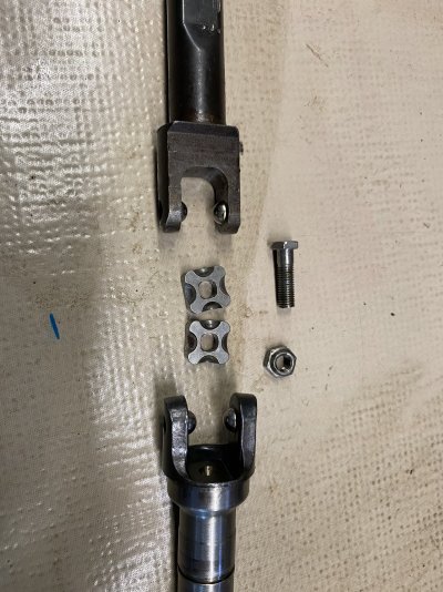
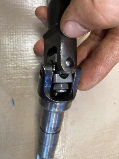
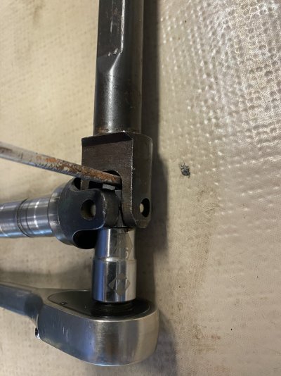
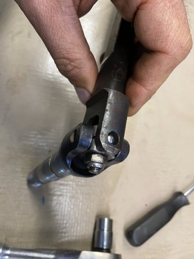
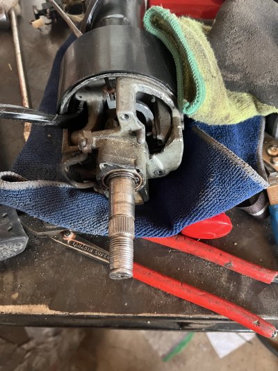
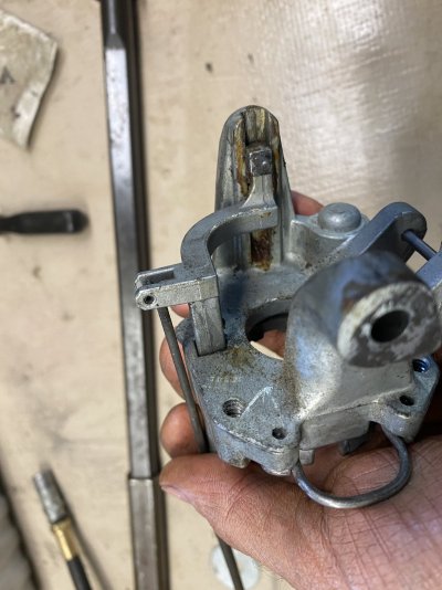
I spent most of three days trying to reduce free play. It does have a real U joint. I am guessing it is something they stuffed in a non tilt unit, and that was the best they could do with the space that was available. There are are four balls. They are not all the same size. How they are placed affects free play.

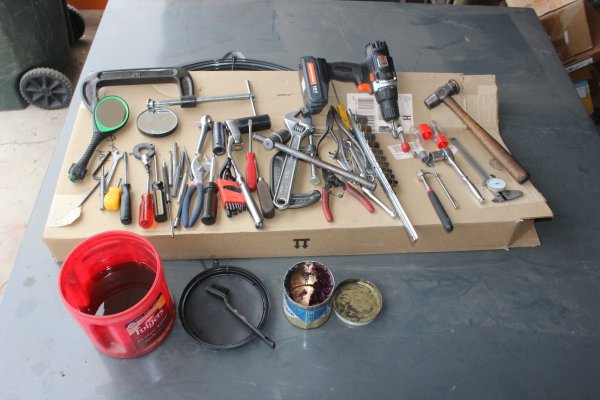
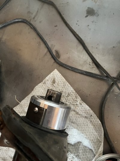
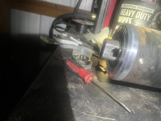
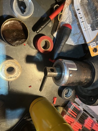
I used everything shown in the pic below.

Then again, if you have a unit like the 0636 pic in the Oct 16 post, then maybe you do have a real U joint.
 

Attachments

  • IMG_9574.JPG
    IMG_9574.JPG
    264.3 KB · Views: 11
Last edited:

david85

Full Access Member
Joined
Feb 21, 2008
Posts
4,829
Reaction score
1,094
Location
Campbell River, B.C.
The "U-Joint" (air quotes, since it's not technically a true U-joint), can also be adjusted for tightness. That's what the locknut does. It doesn't look very strong compared to modern columns that have actual U-joints, but I've never heard of one ever failing. And like almost everything else on these trucks, it is adjustable, so I won't complain.
I thought I already posed photos of this but I guess not. Here's how the U-joint goes together in case anyone is wondering. I searched the web for any photos before tearing mine apart an came up empty.
 

Attachments

  • IMG_0626.JPG
    IMG_0626.JPG
    493.6 KB · Views: 14
  • IMG_0627.JPG
    IMG_0627.JPG
    223.1 KB · Views: 14
  • IMG_0628.JPG
    IMG_0628.JPG
    326.8 KB · Views: 13
  • IMG_0629.JPG
    IMG_0629.JPG
    215.8 KB · Views: 14

Austin86250

Full Access Member
Joined
Oct 5, 2021
Posts
836
Reaction score
473
Location
idaho
Got the bearings in, feels amazing but it seems the bolt holes for the steering shift are too recessed into the bearing, thoughts?
 

Attachments

  • IMG_1937.jpeg
    IMG_1937.jpeg
    261.9 KB · Views: 10
  • IMG_1936.jpeg
    IMG_1936.jpeg
    427.8 KB · Views: 10

david85

Full Access Member
Joined
Feb 21, 2008
Posts
4,829
Reaction score
1,094
Location
Campbell River, B.C.
That part of the shaft is collapsible into the column. It's normally quite stiff, but you should be able to pull out enough length to properly attach the steering box shaft.

EDIT: I never took a dedicated photo, but if you look in the background of this one, you can see the telescoping section of the lower steering column shaft. As a side note, this part can also be the source of slack in the steering. Slop is taken up by a leaf spring inside the slip coupling. If that breaks, you get more slop in your steering.
 

Attachments

  • IMG_0632.JPG
    IMG_0632.JPG
    269.4 KB · Views: 11

Austin86250

Full Access Member
Joined
Oct 5, 2021
Posts
836
Reaction score
473
Location
idaho
That part of the shaft is collapsible into the column. It's normally quite stiff, but you should be able to pull out enough length to properly attach the steering box shaft.

EDIT: I never took a dedicated photo, but if you look in the background of this one, you can see the telescoping section of the lower steering column shaft. As a side note, this part can also be the source of slack in the steering. Slop is taken up by a leaf spring inside the slip coupling. If that breaks, you get more slop in your steering.
My question was more the bolt holes for the shaft to column bolts
 

Attachments

  • IMG_1941.jpeg
    IMG_1941.jpeg
    257.9 KB · Views: 6

Austin86250

Full Access Member
Joined
Oct 5, 2021
Posts
836
Reaction score
473
Location
idaho
See how much farther this is out
 

Attachments

  • IMG_1942.jpeg
    IMG_1942.jpeg
    207.9 KB · Views: 9

chillman88

Supporting Member
Supporting Member
Joined
Feb 22, 2017
Posts
6,027
Reaction score
6,155
Location
Central NY
My question was more the bolt holes for the shaft to column bolts

His reply is still correct for that part. That shaft is collapsible as well. Put a screwdriver through the holes and you should be able to get it to pull out a little bit more. If you can't, you may need to pull that bearing back off and clean up the shaft gently with some sandpaper. You might have a little bit of surface rust or something holding it back.

I had a similar issue with mine when swapping out the lower bearing.
 

Rdnck84_03

Full Access Member
Joined
Jan 15, 2019
Posts
1,126
Reaction score
1,209
Location
Kansas
That part of the shaft is collapsible into the column. It's normally quite stiff, but you should be able to pull out enough length to properly attach the steering box shaft.
I almost said that last night but it has been so long since I have been into the bottom of one that I couldn't remember if it was collapsible or not.

James
 

Austin86250

Full Access Member
Joined
Oct 5, 2021
Posts
836
Reaction score
473
Location
idaho
Ah ok, I though you where talking about the the normal steering shaft, thank you!
 

The_Josh_Bear

Full Access Member
Joined
Jun 1, 2016
Posts
1,930
Reaction score
1,510
Location
Western WA
I thought I already posed photos of this but I guess not. Here's how the U-joint goes together in case anyone is wondering. I searched the web for any photos before tearing mine apart an came up empty.
How friggin cool is that!?!? I've never seen that joint myself(maybe my 89 doesn't have one) but the fact that it's adjustable is so sweet. Love it.
 

Austin86250

Full Access Member
Joined
Oct 5, 2021
Posts
836
Reaction score
473
Location
idaho
I am very pleased to say it went very successfully wasn’t nearly as bad as I thought it be
@david85 you should really make a right up about these steering columns you where extremely helpful
I guess I’m back off to the alignment shop for the second time in 2 weeks LOL the steering shafts and or wheels are keyed differently
 

Attachments

  • IMG_1983.jpeg
    IMG_1983.jpeg
    440.3 KB · Views: 9
  • IMG_1985.jpeg
    IMG_1985.jpeg
    303.6 KB · Views: 7
Last edited:

Austin86250

Full Access Member
Joined
Oct 5, 2021
Posts
836
Reaction score
473
Location
idaho
xc_hide_links_from_guests_guests_error_hide_media
I guess I spoke too soon, looks to be an intermediate No fss while crank? The accessories I have powered by the fss triggered relay help me come to that conclusion
Only thing that comes to mind is the ignition switch? It’s new and by that I mean within the time I’ve had it worked great all day until I slapped it back on this column

EDIT: used a power probe confirms loss of power at crank and when I got wire the fss it works as should
 
Last edited:

Forum statistics

Threads
91,284
Posts
1,129,801
Members
24,101
Latest member
dieselmainiac

Members online

Top