I'm out of my depth

madpogue

Full Access Member
Joined
Mar 16, 2009
Posts
1,707
Reaction score
169
Location
Madison, WI USA
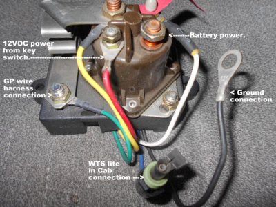
The starter solenoid is on the starter. Those are relays. The one that's in use is the starter relay. That rear-most terminal also acts as a junction point for everything electrical on the truck, except the starter motor. It doesn't use the relay's circuits, it's just a convenient post.

Anybody's guess what the OP used the other relay for. It may well have been the original failed starter relay, and the OP was unable (or too lazy) to remove it.

Are there wires connected to both small terminals?
 

rdoimages

Full Access Member
Joined
Sep 12, 2015
Posts
145
Reaction score
1
Location
Kingsland, GA
There are wires connected to both small terminals on the 4 post relay


Sent from my iPad using Tapatalk
 

rdoimages

Full Access Member
Joined
Sep 12, 2015
Posts
145
Reaction score
1
Location
Kingsland, GA
The red goes to the battery, the green appears to split and goes to the harness around the alternator area, the two yellows are def part of the gp harness, the one on the small post I assume goes to the ignition. The yellow crimp was where the PO had the wire going to the switch and then it came back from the switch and tapped into the seemingly home brewed gp harness.
 

madpogue

Full Access Member
Joined
Mar 16, 2009
Posts
1,707
Reaction score
169
Location
Madison, WI USA
The red goes to the battery, the green appears to split and goes to the harness around the alternator area, the two yellows are def part of the gp harness
That's the junction point I referred to above.

the one on the small post I assume goes to the ignition.
That's the one that's energized when you turn the key to the START position. That's the trigger circuit for the relay.

The large terminal with the single wire, that wire should go to the starter solenoid (the actual solenoid _on_ the starter). Why it's the one that's ganged to the other phantom relay is anyone's guess.

The yellow crimp was where the PO had the wire going to the switch and then it came back from the switch and tapped into the seemingly home brewed gp harness.
Sounds like a badly hacked manual GP control setup.
 

rdoimages

Full Access Member
Joined
Sep 12, 2015
Posts
145
Reaction score
1
Location
Kingsland, GA
Surfing the net last night I found a really good diagram of a wired up controller and now I can't find it [emoji34]. My controller is totally gone and the original wiring looks to be taped off. Keep in mind it's buried under the ATS turbo and very challenging to access. Before I try to reroute it to mount a new controller in a more accessible location, I'm trying to make sure I'm dealing with the correct wires. Can anyone help me with a photo, wire colors, etc. I've searched the posts and can't find it.


Sent from my iPad using Tapatalk
 

no mufflers

Full Access Member
Joined
Jan 20, 2014
Posts
2,238
Reaction score
1,088
Location
rhode island
I relocated my glow plug relay to the plastic inner fender, much easier to get to. I used two harnesses to get the extra length. I can post some picks up later.
 

OLDBULL8

Good Morning Ya'll.
Joined
Feb 12, 2009
Posts
9,923
Reaction score
342
Location
Delphos , Ohio
This might help ya.

If your going to use just a relay to power the GP's with a manual push button, make sure it's a GP relay and not just a starter relay. The contacts in a GP relay are heavier. Both, a starter and a GP relay are grounded internally, some brands of relays do have the two small posts, if the relay is not mounted to the chassis, then the second post (grounding) has to be used for a ground (Neg).
 

Attachments

  • 87 up Glow plug system.jpg
    87 up Glow plug system.jpg
    71.8 KB · Views: 7
  • DSCN0686.JPG
    DSCN0686.JPG
    81.8 KB · Views: 8
Last edited:

rdoimages

Full Access Member
Joined
Sep 12, 2015
Posts
145
Reaction score
1
Location
Kingsland, GA
Battery power is provided by the double yellow wire is my understanding. I have got the wts plug, the original brown gp wires are there (cut and useless, but there) and there is an additional red wire with a blue? Stripe that I guess I should test to see if it's power from key switch. Is that the full extent of the wiring?


Sent from my iPad using Tapatalk
 

rdoimages

Full Access Member
Joined
Sep 12, 2015
Posts
145
Reaction score
1
Location
Kingsland, GA
I'm 99% sure I've properly identified all the relevant wiring, I now need to get it from the current location under the turbo on the back of the manifold to the inner fender. I think I'm just going to go back to letting the controller do all the work (easier for the wife and kids) rather than keep a momentary switch. I hate cutting wires, but getting the harness from under the turbo without removing the turbo may prove to be impossible.


Sent from my iPad using Tapatalk
 

riotwarrior

Full Access Member
Joined
Sep 19, 2006
Posts
14,782
Reaction score
492
Location
Cawston BC. Canada
I am really beginning to think it may be an advantage to source either a new replacement GP harness and engine harness with gp controller complet rather than messing with the current epically craptastic stuff you have.

I know when I redid my GP harnes with new bullets and such it was a fair jit of work making it all work but the end result is a functioning system.

Are there any recycling yarads in your area that you can maybe sorce a harness from?

If not surely one of the members might be able to help

JM2CW
 

Latest posts

Forum statistics

Threads
93,029
Posts
1,156,233
Members
26,618
Latest member
Nathanelliott44

Members online

Top