6.9 IDI valve train questions + head gasket job

8769bigred

Registered User
Joined
Nov 5, 2024
Posts
38
Reaction score
17
Location
Portland Oregon
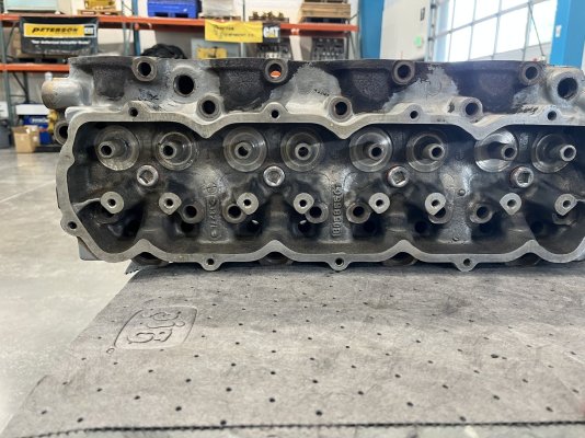
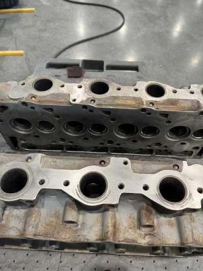
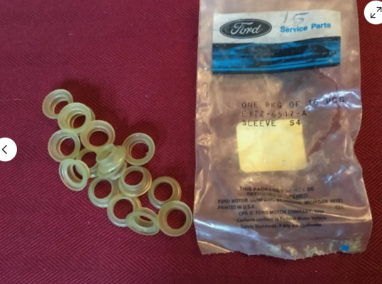
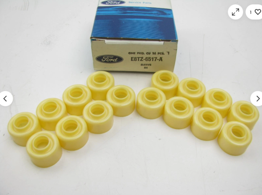
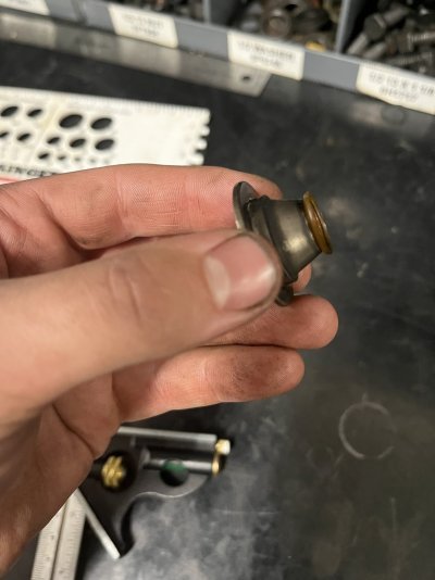
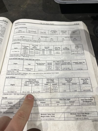
I also got my cylinder heads nice and clean today. Once my new exhaust valves are here I’m going to sit down and measure all the clearances. Got a quote from a shop today to do a valve job and they wanted 900$. That seemed a bit high. I’m going to have to shop around.
 

Attachments

  • IMG_9004.jpeg
    IMG_9004.jpeg
    413.7 KB · Views: 4
  • IMG_9005.jpeg
    IMG_9005.jpeg
    367.3 KB · Views: 4

Nero

HD Diesel nut
Joined
Jan 3, 2022
Posts
4,161
Reaction score
4,714
Location
OR
Shop around, the shop that did the valve grind on my v8 jeep heads only charged $42 per head, but I also had both heads machined, total bill was $280 for machine and valve grind....


Ah heck, I see you're in Portland... Give the guy I used a call for a quote,
Hutchins Performance Machine and Welding
5740 SW 56th Ave
Portland, Or 97221
5032467144
 

8769bigred

Registered User
Joined
Nov 5, 2024
Posts
38
Reaction score
17
Location
Portland Oregon
Ok I have done some more research on the little plastic piece on my valve spring cap/retainer.

Here is a breakdown of the ford illustration for the 6.9 IDI valve train.

I believe part 6517 (E3TZ-6517-A) is the piece I need. Ford calls it 'oil sleeve' and it appears that 1983-1987 (6.9 IDI) you need 16 of them. One for each valve. This makes sense because they were on both intake and exhaust valves on my engine, at least what was left of them. I'm not sure what the purpose of this part is? Maybe to hold oil on top of the valve stem for lubrication?

Then it appears in 1988 (7.3 IDI) they changed to only requiring them in the exhaust valves and changed the part number to E8TZ-6517-A This part number looks significantly different than the E3TZ-6517-A that is found on the 6.9 from 1983-1987

I have 'upgraded' valve stem seals for all 16 cylinders from classic diesel design. I'm wondering if these seals eliminate the necessity of E3TZ-6517-A.

One thought I had was that in 1983-87 they just put the 'oil sleeve' on all the valve spring caps to ease manufacturing. Since the part was removed from the intake valves in 88 and changed to a new part for the exhaust valves it makes me think it has less to do with lubrication and more to do with preventing oil from intruding into the combustion chamber via the valve guides.

Thoughts?
 

Attachments

  • 6.9 idi 6517 part numbers.PNG
    6.9 idi 6517 part numbers.PNG
    119.7 KB · Views: 6
  • 6.9 idi 6517.PNG
    6.9 idi 6517.PNG
    206 KB · Views: 6
  • e3tz-6517-a.PNG
    e3tz-6517-a.PNG
    1 MB · Views: 8
  • e8tz-6517-a.PNG
    e8tz-6517-a.PNG
    666.3 KB · Views: 8
  • spirng cap with 6517.jpg
    spirng cap with 6517.jpg
    31.1 KB · Views: 7

Nero

HD Diesel nut
Joined
Jan 3, 2022
Posts
4,161
Reaction score
4,714
Location
OR
When I redid my heads and the ones on my dads truck, I just put regular push on stem seals, no need to overcomplicate things.
 

Nero

HD Diesel nut
Joined
Jan 3, 2022
Posts
4,161
Reaction score
4,714
Location
OR
@Nero ok I see. So all these different seal pieces are just the old style valve stem sealing system.
Correct. I think you can still get them, but I went with just regular style seals, so far no issue. I used a basic Felpro upper gasket set, and it came with them.
 

8769bigred

Registered User
Joined
Nov 5, 2024
Posts
38
Reaction score
17
Location
Portland Oregon
@rreegg I have a a 7.3 FSM and it looks like the 7.3 idi valve spring spec is 80 pounds at 1.833 inches compared to the 6.9 spec of 60 pounds at 1.790 inches. Maybe I have some updated springs because it was the second to last year of the 6.9? Not sure.
 

Attachments

  • image.jpg
    image.jpg
    359.8 KB · Views: 4

8769bigred

Registered User
Joined
Nov 5, 2024
Posts
38
Reaction score
17
Location
Portland Oregon
Made a bit of progress today. Spent the morning getting a core support for the truck at the junk yard and then dropping it off at the sand blaster. I discovered I have a stupid 37”x15” radiator that is hard to buy a replacement for (mine was leaking) so I decided to upgrade. I will now have the “super cooling” upgraded radiator and more clearance for a intercooler.

On the engine I worked on the front cover, the top water pump weld nuts were stripped out so I cut them off. I will weld new ones on. I also cleaned all the head bolt holes in the block. They have been soaking woth ATF/aceton for a few days. I made a home made thread chaser with a head bolt. This worked really well and all the threads feel smooth. Another note on head bolt holes for future readers. Be sure to check the holes in the head. Some of mine had a TON of rust and crap that was really stuck on. You will need a high quality wire bore brush and several rounds of cleaning.
 

Attachments

  • IMG_9024.jpeg
    IMG_9024.jpeg
    175 KB · Views: 5
  • IMG_9023.jpeg
    IMG_9023.jpeg
    307.5 KB · Views: 4
  • IMG_9021.jpeg
    IMG_9021.jpeg
    244.1 KB · Views: 4

IDIBRONCO

IDIBRONCO
Joined
Feb 5, 2010
Posts
14,976
Reaction score
14,075
Location
edmond, ks
Another note on head bolt holes for future readers. Be sure to check the holes in the head. Some of mine had a TON of rust and crap that was really stuck on. You will need a high quality wire bore brush and several rounds of cleaning.
Those are usually the bottom row of bolts. If you look while the heads are on, those bolts and holes are exposed. Yes the head bolt thread cleaner works well. That's what we used when I worked on these for a living.
 

8769bigred

Registered User
Joined
Nov 5, 2024
Posts
38
Reaction score
17
Location
Portland Oregon
Back into the water pump weld nuts this afternoon after messing with the new to me core support.

I purchased some weld nuts from the hardware store and they are taller than the originals but the injection pump gear seems to clear them ok. Under normal operation that gear should never wander. I did find some square ones that may be thinner but I’m not sure. Might need to order some just to have some peace of mind.

the bolts that came with my OEM water pump are also not long enough to utilize these weld nuts. I’m thinking the ford ones did not have the bosses where the weld is supposed to be applied
 

Attachments

  • IMG_9041.jpeg
    IMG_9041.jpeg
    229.7 KB · Views: 5
  • IMG_9039.jpeg
    IMG_9039.jpeg
    273.2 KB · Views: 5

rreegg

IDI n TDI
Supporting Member
Joined
Feb 10, 2022
Posts
662
Reaction score
391
Location
Puget Sound
Is a weld nut a specialty part or just a nut that’s welded to allow bolt to thread? I did an idi water pump this past winter but never removed the cover so not sure what the interior looks like.
I’m curious what the bolts thread into from the factory and how your situation arose. Figured it was just a tapped casing or something
I remember reading the w/p depth has changed over the years and bolt lengths are different depending on original or updated design

Just wondering

Edit : reread a bit and missed the part where they were previously stripped so you cut them. I’m too lazy to delete the above so will just leave it nothing to see here :frustrate
 

8769bigred

Registered User
Joined
Nov 5, 2024
Posts
38
Reaction score
17
Location
Portland Oregon
Well I got some valve guide measurements

First thing I did was set my hole gauge to .3775. This is .0055 over my new exhaust valve stem size. This basically created a yes no check for my guides. I could not get the ball gauge into the top of the guides. I could get the ball gauge about 1/8-1/4 inch into the bottom of the guide by the combustion chamber but no further than that. The guides definitely wear unevenly.

I then measured the best I could favoring the ‘larger’ bottom of the guides bore. I subtracted my stem size from each cylinders guide and then recorded the result.

The second method I tried was to set the head flat on the bench and then slightly lift the valve off the bench, but not close it. I then pushed the valve all the way towards the intake manifold, zeroed the gauge and then pushed the valve towards the exhaust manifold. I recorded the value and divided it by two. This method mirrors the ford service manual procedure.

The problem with the dial indicator method I found is that I don’t have the tool ford says to attach to the valve stem. The tool ford says to use clamps on the valve stem and then it lets the stem drop to a specified depth. Then you wiggle the stem like I did.

As the valve begins to extend out of the guide it can ‘wiggle’ more. The problem I have is not knowing the specific amount that the valve should ‘open’ before taking the dial indicator reading.

Long winded I know, but these things are.

Any input would be great!
 

Attachments

  • IMG_9057.jpeg
    IMG_9057.jpeg
    259.8 KB · Views: 1
  • IMG_9056.jpeg
    IMG_9056.jpeg
    375.2 KB · Views: 1
  • IMG_9049.jpeg
    IMG_9049.jpeg
    373.1 KB · Views: 1

Forum statistics

Threads
92,927
Posts
1,155,095
Members
26,426
Latest member
msmith910

Members online

Top