Removing Timing Cover

Sparks-IDI

Registered User
Joined
Sep 20, 2022
Posts
24
Reaction score
13
Location
Melbourne, FL
Hi all,
First time posting. Have been following this site awhile and have learned a lot.

I picked up a 1994 F-250 HD Vin K regular cab 4x4 at a good price. I have been going thru it systematically fixing all the things that needs to be done. It was a turbo truck but somewhere in the past the motor was replaced with a NA IDI. It seems to run fine.
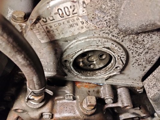
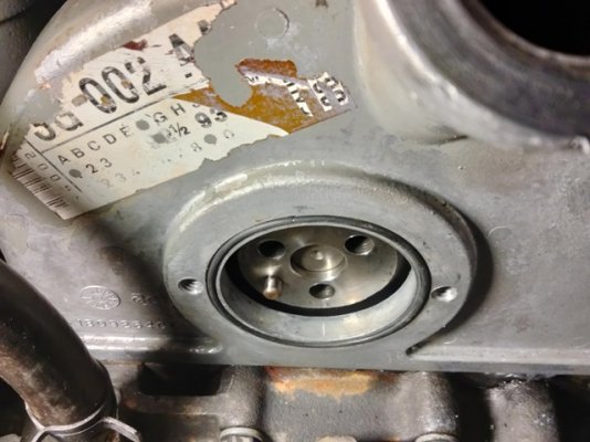
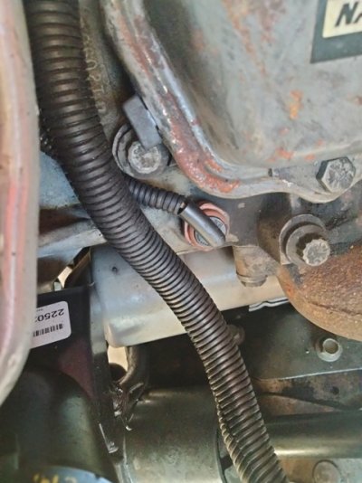
I have pressure washed the whole engine compartment as it was very oily when I picked it up. Now with it cleaned up I am tracking down where the oil leaks are. Dipstick tube was one, that's fixed now. The other is at the bottom of the injector gear cover above the water pump. It leaks actually quite a bit. I now see how the whole engine compartment got oily. The fan picks up the oil and sprays it everywhere.

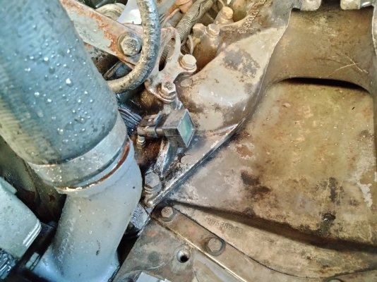
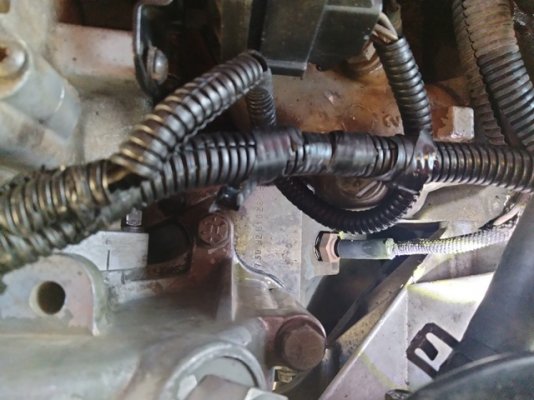
My question is, can I just lift the cover and injector pump off as one piece? I have un-done the fuel supply lines at the injectors and want to lift the cover, pump,lines and cam gear out as one. It would save me horsing around trying to get the injector pump off. That can then be done on the bench. I figure when reassembling I should be able to align the gear timing marks. Can you see both marks with this top cover removed? Also, what is used to seal this cover to the block? Looks like someone previously used RTV. Is there a paper gasket used or an o-ring?

I have not removed it yet because I wanted to be sure I can re-align the timing marks without removing any more covers or hardware.
 

Attachments

  • Timing Cover01.jpg
    Timing Cover01.jpg
    150 KB · Views: 19

hacked89

Full Access Member
Joined
May 30, 2018
Posts
1,738
Reaction score
2,328
Location
Bucks County PA
Is it possible to lift the cover without bumping the gear? Yes
Is it possible to realign the gear without taking the front cover off? Yes
Is it easy to do? No, you’ll be using mirrors and feeling around with a pick

Your last question - RTV
 

Black dawg

Registered User
Joined
Jan 9, 2006
Posts
3,995
Reaction score
703
Location
sw mt
mark balancer so you know engine didnt turn while it was apart, and mark gear location to cover so that you know pump gear is back in the same spot. Need to be very precise with all marking.
 

ROCK HARVEY

Full Access Member
Joined
Oct 3, 2021
Posts
417
Reaction score
372
Location
Dayton OH
If you’re trying to prevent oil messes, check your oil fill cap as well. Mine was missing the rubber seal, and had allowed blowby oil mist to leak out and coat everything.
 

Sparks-IDI

Registered User
Joined
Sep 20, 2022
Posts
24
Reaction score
13
Location
Melbourne, FL
Want to thank you all for responding to my questions. I went ahead and scribed a line on the cam gear and cover to help in getting the gear reinstalled properly. It's a good thing as after I pulled it apart I don't see how one could confidently be sure you would get the timing marks together as the mating gear is really way down there without much room to see the mating mark. Just don't turn the motor while it is apart.

Could someone help identify what the other pictures are? The potted chip I can only guess is perhaps a timer chip for the high idle solenoid. If not what is it and for what. If not for the solenoid, what controls and tells the solenoid to turn off?

The other two pictures look like temperature sensors, but two? They look identical. One is in the block by the engine serial no. and the other is in the drivers side head. Which if either work the dash temp gauge?
 

Attachments

  • Timing Cover Marked.jpg
    Timing Cover Marked.jpg
    117.9 KB · Views: 36
  • Potted Chip.jpg
    Potted Chip.jpg
    350 KB · Views: 35
  • Sensor 01.jpg
    Sensor 01.jpg
    119.2 KB · Views: 31
  • Sensor 02.jpg
    Sensor 02.jpg
    119.9 KB · Views: 33

Black dawg

Registered User
Joined
Jan 9, 2006
Posts
3,995
Reaction score
703
Location
sw mt
The sender in the head is over temp light, the one up farther is for the temp gauge. I dont know what the other thing is.
 

Black dawg

Registered User
Joined
Jan 9, 2006
Posts
3,995
Reaction score
703
Location
sw mt
Is that An oring on the front of the timing cover, I always wanted to try one there, but figured that plate wasnt stiff enough to work with one.
 

IDIBRONCO

IDIBRONCO
Joined
Feb 5, 2010
Posts
12,235
Reaction score
10,925
Location
edmond, ks
Potted chip? That's a new one on me. Whatever it's called, I believe that it has something to do with the fuel heater. The sender to control the fast idle/timing advance is right next to it. When it's unplugged, there's two flat prongs that stick up. The sender is slightly forward of the pictured item.
 

Sparks-IDI

Registered User
Joined
Sep 20, 2022
Posts
24
Reaction score
13
Location
Melbourne, FL
Black Dawg,

Yes, I used some oring stock from my business. The groove depth on the cover measures nominally .063. I keep oring cord stock of various diameters for the work I do. I used 2 mm (.078) Buna N stock. The idea of smearing RTV seemed so dumb when there was a groove to be used. Cord stock plus super glue works! I have assembled it all and no leaks and all is good.
 

IDIBRONCO

IDIBRONCO
Joined
Feb 5, 2010
Posts
12,235
Reaction score
10,925
Location
edmond, ks
Darn. I was wrong. I guess that's what I get for only driving Brick Nose trucks so far.
 

snicklas

6.0 and Loving It!!
Staff member
Joined
Aug 7, 2006
Posts
6,164
Reaction score
2,342
Location
Greenfield, Indiana
Darn. I was wrong. I guess that's what I get for only driving Brick Nose trucks so far.

Yea that's a 7.3 thing (and maybe an 87 6.9) Not sure how the one on the 6.9 Bull nose trucks work, since the factory water separator and water in fuel light is from the can on the firewall, instead of being part of the filter.

The only 6.9 bull we've had so far, was "7.3-ized" by Travis. It had a 7.3 head and a 7.3 glow plug controller on it.
 

Isaac Ristow

Full Access Member
Joined
Jul 11, 2018
Posts
234
Reaction score
158
Location
Somerset Wisconsin
I want to add that I learned a trick from brian and it backfired on me because I did it wrong doing this exact fix on mine I ended up using a buffed/polished butter knife to use as a mirror to align the timing marks for the ip gear. But the trick is to get some longer 5/16-16 bolts all thread grind them to a dull point and put them in the ip gear bolt access cover threads run them in finger tight than a touch more this locks the injection pump gear to the housing but what i messed up with is the gear has slots cut in it and my locking bolts missed the gear face and went through the slot onto the back side of the ip gear housing and the gear turned, So you need to make sure they contact the gear. Then obviously undo the injection lines at the injectors and everything else connected to the ip you can lift it off connected to the housing and clean everything up use permatex right stuff or ultra grey.
 
Top