Luke_IDI
Registered User
Ok, finally managed to assemble a few different adapters, a grease whip, and a 3000 psi gauge to look at ICP manually.
The ICP sensor thread is M12x1.50. The seal is with an O Ring as with the sensor. My local hydraulic shop had this fitting to JIC, then JIC to 3/8” pipe, 3/8” pipe to 1/8” pipe, grease whip (rated 3000 psi), 1/8” pipe to 1/4” pipe, gauge.
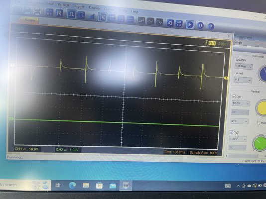
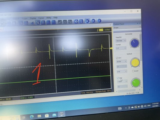
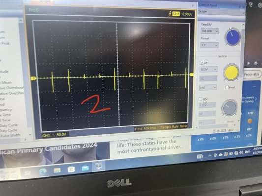
As verified by the mechanical gauge, ICP does indeed rise to 3000 psi in a matter of a couple of seconds. So to answer the first part of my original question, the ICP is reading correctly.
Is it possible to see rising values like this when they do not correspond to actual pressure? I can’t say for sure. I have heard a mention or two that an electrical issue could cause that situation, but I’m not sure what.
Where this stays interesting is: why is the PCM commanding full IPR duty cycle?
Thanks to everyone who posted. I’m going to copy this into my other thread, “Slow Crank…” and continue updating about the diagnostic process there. To be continued…
The ICP sensor thread is M12x1.50. The seal is with an O Ring as with the sensor. My local hydraulic shop had this fitting to JIC, then JIC to 3/8” pipe, 3/8” pipe to 1/8” pipe, grease whip (rated 3000 psi), 1/8” pipe to 1/4” pipe, gauge.
As verified by the mechanical gauge, ICP does indeed rise to 3000 psi in a matter of a couple of seconds. So to answer the first part of my original question, the ICP is reading correctly.
Is it possible to see rising values like this when they do not correspond to actual pressure? I can’t say for sure. I have heard a mention or two that an electrical issue could cause that situation, but I’m not sure what.
Where this stays interesting is: why is the PCM commanding full IPR duty cycle?
Thanks to everyone who posted. I’m going to copy this into my other thread, “Slow Crank…” and continue updating about the diagnostic process there. To be continued…