Questions regarding re-wiring glow plug harness...

dozer

Full Access Member
Joined
Mar 31, 2005
Posts
117
Reaction score
0
Location
sw Oregon
OK, now -I'm- a little confused...

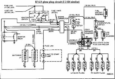
I thought the 7.3 GPC screwed into the engine, just like the 6.9, and has a temp-sensor built into the bottom of it to sense engine temp ??

Or did I miss something in IDI's 101 ?? LOL

If so, mounting it elsewhere will affect the op of the GPC. Offhand, I don't think it'll -hurt- anything...but your GP's would run a full cycle even when starting a hot engine.

Regarding the current.... Yes, you've hit the nail on the head. FIRST you have to determine what the current draw per GP is going to be. And all I can tell you is that the plugs in my 7.3 draw 30-35 amps each during the first second or two....decreasing to around 20 amps each after 7-8 seconds.

If I recall correctly, Birken said that his 7.3 GP's were in this neighborhood also.

On a 4.5 digit Fluke DMM, my 7.3 plugs measure .10 ohms, with the meter-lead resistance zeroed out first.

On those 8-position fuseblocks...just to reiterate....all of them that I've seen and used are only rated for 60-80 amps -total-. I'm sure they'll work fine at first. What I don't know is how -long- they'll work fine, and what will happen when things get old and corroded... May still be fine...I just don't know. Check the -total- input rating of the block you want to use, and make your own decision there.

These tab-type fuses are made in another bigger size...up to at least 60 amps (biggest I've seen so far). They're about an inch long, and 3/16 thick. I haven't seen in-line holders for them, but I haven't looked yet either.

If it were me doing it, and someday I might be, and if in-line holders are available, I'd probably crimp ring-terminals onto 8 of 'em, use 40 amp fuses, and stack the rings right on the output-post of the relay. I'd use a short piece of #4 between the batt and relay input; and I'd use #8 for the GP runs.

Simple, cheap, pretty safe, and builds in the ability to easily test the GP's individually, and while standing comfortably beside the fender. ;Sweet

Also, if you have to pull the motor, a single nut off that stud frees the harness to be lifted out with the motor.

As far as looks....well, it might not be the most sanitary looking thing...but a couple minutes with tie-wraps to keep the fuseholders stacked together, and
I don't think it'd look too bad.

hope this helps a bit Warden. Can't think of anything else to suggest. Start by verifying just what your max amps per GP is going to be, and take it from there...

Richard
 

The Warden

MiB Impersonator
Supporting Member
Joined
Jan 12, 2005
Posts
7,356
Reaction score
35
Location
Fog Bless Pacifica (CA)
Richard,

IIRC, the 7.3l controller bolts to the bar running along the back side of the intake manifold originally...and, even if I wanted to put it there, my turbo's in the way. The mounting points are actually plastic, and there's nothing I can see that appears to directly measure engine temperature.

Someone told me that the 7.3l controller measures the resistance through the plugs themselves, and it somehow uses that resistance to figure how warm the combustion chamber is, and works from there. This is why I've been asking about how the wires and whatnot are going to affect the controller's operation. :) I could be remembering this whole thing wrong, but if I'm right, that's why the location of the controller is not a problem.

The 8-spot fuse block I found (take a look here) appears to be able to handle a total of 150 amps...which may still not be enough, but is at least better than 80. :)

I've seen the "super-sized" blade fuses as well, and West Marine's got 'em up to 80 amps. The bad news is, the only fuse block in their catalog that'll take this type of fuse only can handle one circuit, and costs $20 :shocked: and they don't have any inline holders either. Maybe a different holder is available elsewhere; I haven't looked online yet (just at the WM catalog)...

My voltmeter doesn't have the capability to measure amperage, at least not to my knowledge. :( So, I'm not sure how I'm going to handle that...but, at this point, that's mainly for fuses...8 gauge wire for each plug doesn't sound too unreasonable. I just have to figure out how to make the wire go into a female bullet connector that's meant to take 12 gauge wire *lol*

Thanks again :cool
 

tuckerd1

WAR DAMN EAGLE!
Joined
Mar 9, 2005
Posts
903
Reaction score
0
Location
Princeton, AL
Looking at the schematic below, 10awg wire goes from controller to GPs.

Don
 

Attachments

  • 28385GP_87-94_controller.jpg
    28385GP_87-94_controller.jpg
    76.5 KB · Views: 67

The Warden

MiB Impersonator
Supporting Member
Joined
Jan 12, 2005
Posts
7,356
Reaction score
35
Location
Fog Bless Pacifica (CA)
Don, good point there...that means that 8 AWG wire should be able to handle an individual plug without a problem. :D

Your diagram raises another question, though, on a semi-related subject...if I'm reading the diagram correctly, on the OEM circuit, a wire comes off the "RUN" circuit of the keyswitch and splits off into two wires. One of these wires powers the cold-idle solenoid and the fuel heater. The other wire goes through the WAIT TO START light and powers the controller. Am I reading the diagram correctly?

If I am, I assume that the controller somehow provides a ground to the WTS light when the light's supposed to be on, and somehow cuts off the ground to the light when the light's supposed to be off...but, IIRC, the controller will cycle the plugs for a short time even after the WTS light is off?

After seeing part of a setup sitting on an engine, I had assumed that the power feed to the controller went to one of the terminals on the relay, and the blue line just sent 12 volts to the WTS light when the light's supposed to be on. This diagram seems to contradict that, though...the line that I had thought was the power feed looks to be what powers the fuel shut-off solenoid.

Anyone who's looked at a 7.3l wiring harness in detail (or can read a wiring diagram better than me :)) have any comments on this?

And, back to the original question...from what Richard's saying, it sounds like one 40 amp fuse for each G/P will handle the system safely. If anyone feels otherwise, please speak up :) I'm probably going to be getting parts in the next few days...

Thank you all again for your patience :cool I know I could just wire it up and call it good, but I'd rather take the time and get the system working the way it's supposed to, so I hopefully won't have to mess with it again. The WTS light, for example, is one of those "little details" that probably means more to me than most ;)
 
Last edited:

tuckerd1

WAR DAMN EAGLE!
Joined
Mar 9, 2005
Posts
903
Reaction score
0
Location
Princeton, AL
I think 8ga to each gp is overkill. If I were going to run individual wires I would go with 10ga, possibly 12ga. Look like from this diagram you could run a 10ga to each bank of gps and splice each gp from the 10ga wire. I'll check my truck tomorrow and try to determine the wire size to the gp.

While i have not disassembled and tested a gp circuit, the way I read the diagram is the controller is powered thru a 6ga wire that is split at a terminal into 2 10ga wires (60amp equiv). The controller power is turned on/off from the ig sw thru internal controller ckts (probably power diodes). The WTS light is turned on/off thru the wire you speak of by the controller.

Don
 

The Warden

MiB Impersonator
Supporting Member
Joined
Jan 12, 2005
Posts
7,356
Reaction score
35
Location
Fog Bless Pacifica (CA)
tuckerd1 said:
The controller power is turned on/off from the ig sw thru internal controller ckts (probably power diodes). The WTS light is turned on/off thru the wire you speak of by the controller.
Where does the controller power (switched power) attach to on the controller?
 

tuckerd1

WAR DAMN EAGLE!
Joined
Mar 9, 2005
Posts
903
Reaction score
0
Location
Princeton, AL
The Warden said:
Where does the controller power (switched power) attach to on the controller?

This is a WAG. If anyone has a description of operation from Ford, please post it and correct me if I'm wrong.

The switched power is available to the controller/GPs from the 2-10ga wires shown to the left of the controller. The 20ga wires leaving the ign sw go thru the engine connector and exits as a 2-16ga wire that supplies a switch signal to the controller and (it appears) power to the Fuel Shutoff sol, Fuel Line hHeater, the Engine Temp sw> thru which supplies power to the Low Idle sol and Cold Advance sol. Also 1-20ga wire goes to the WTS light which then goes to the controller. This wire is is just a signal wire too.

As the ign sw is turned on, the WTS light is lit and a voltage signal is applied to an SCR, or equiv. inside the controller to turn on power to the GPs. As power is applied to the GPs, their resistance (R) increases. As their R increases the voltage drop (VD) across the GPs increases. When the VD gets to a certain level it signals the controller to turn off the WTS light and start cycling the GPs. At a preset time (or certain VD) the controller completely turns off the GPs until the ign sw is cycled again.

BTW, I just learned that fusible links are generally sized 4 wire gauge sizes smaller than the wires they are trying to protect. You can install your own fusible links as described HERE

I hope this helps and doesn't muddy the water any more. And if this isn't how the GP ckts work, someone please provide a description as suggested above.

Don
 

jdkline

Full Access Member
Joined
Jan 17, 2005
Posts
78
Reaction score
0
Location
Gainesville, FL, USA
All this sounds pretty complicated, mostly because youa re building a new harness. I ddi a similar conversion, I repeat my offer to help, Time, I think you have my email and phone #. The solid state controller, measures resistance in the glow plug and determines on time thusly. Your glowplugs come on at each startup and burn at leasta full cycle, however, it will not be as long as on a dead cold engine on a cold morning, and likely the glow plugs will not have any afterglow as they do on a cold startup. All depends on if you actually wait for them when teh engine's hot or just crank. I know what you mean about wanting the WTS lamp to work, I've always thought that was acool thing about diesels(weird as that may be, just to be different I guess) on teh 6.9 harness, I'm really not sure how it does it, but anytime there is current to the glow plugs, the light is o-n. With the 7.3 system, the bluw lead from the controller must behooked up properly for that to work, and it's more of a dummy light, it comes on 7-10 seconds each time and goes out when the glow plugs are done, and stays out, never mind the glow plugs often cycle some more after the truck is started, it just doesn't show up on this system. Since I didn't need it, I just left the blue lead hanging, if you design your harness so that it works like teh 6.9 one your truck came with, you can do the same.
 

dozer

Full Access Member
Joined
Mar 31, 2005
Posts
117
Reaction score
0
Location
sw Oregon
Warden, I agree that the 8ga is probably overkill.

However, if I do re-do my 7.3, it will be with connectors for 6.9 style plugs, so that I can use the self-regulating dual-coil type (not available with 7.3 style bullet-tops); and a manual pushbutton instead of the 7.3 GPS.

And the crimp-conns for 3/8" blades (to fit the blade style 6.9 GP's) are available in 8-ga wire capacity. So, that's why I was talking about using 8-ga.

8-ga will also give a little quicker heating GP, and will waste less battery power in the wire.

On the other hand, the total current draw may well be a bit higher during the first few seconds; since the total circuit resistance will be lower with the 8ga vs. 10 or 12.

Hope it helps. Heck....hope you have it done and working already! :D

Richard
 

The Warden

MiB Impersonator
Supporting Member
Joined
Jan 12, 2005
Posts
7,356
Reaction score
35
Location
Fog Bless Pacifica (CA)
Richard, I've been so busy with school over the past few weeks that I haven't even had time to touch the system. :( I still have a bunch of questions regarding the conversion, but I won't be able to sit down and figure things through until finals are done. Hopefully in another 2 or 3 weeks... :)

Thank you all again!! I apologize for the delay...
 

hardknocks

Registered User
Joined
Dec 26, 2004
Posts
27
Reaction score
0
Thread resurected!

Hi guys , I'm trying to bypass my controller . From what I've read , the push-button in the cab will simply open and close the common white wire on the reply?

A little background on my problem : I replaced all glow plus with motocraft , When I turned the key a friend was watching and thought he saw a spark . In any case the wires got to hot to touch on the relay . Also after start the glow plugs still have power . I dint run it long and hopfully all my plugs are still good . ( In all testing I never saw a spark , so I'm not sure about this)

I pulled the relay and hooked it upto 12v . You can hear the seliniod work , and has continuity across the other side of the relay . Funny thing is , once engaged (on the truck anyway) , the battery power and the GP side both measured 10v , while dis-engaged , the batter termminal reads 12v. I figured it was a bad relay , with somthing grounded out , hence the wires getting hot? Sound right?

Well , I bypassed the relay and controler with a 12g wire to a pushbitton in cab , from batter terminal to glowplug terminal .I tied ignition and fuel shutoff together off the relay . Needless to say I fried the switch , which was rated 12v 15amps . After reading this thread I understand why .

My question , do you think I have a bad relay ? And without running a bunch of heavy guage wire , is the only way to bypass the controler with the white ground as a open/close means . And in this case it would require a good working relay correct?
 

Latest posts

Forum statistics

Threads
91,292
Posts
1,129,831
Members
24,106
Latest member
lewisstevey7

Members online

Top