You say the truck is much safer now, but I wonder if the safety you've gained is offset by the increased pedal effort? What if someone small (wife, teenager, old fart) was driving your truck? If they couldn't mash down on the pedal like you can, they won't have as much stopping power. Do you think your vacuum booster was failing and thats why the pedal was mushy? What does mushy mean in this instance? Would it go to the floor?
I would be super interested to see how you felt about the system if you were to only swap the hydro pedal in. If you only move the hydro unit down, the pedal is still going to be massively hard. This doesn't seem that safe to me?
it is extremely offset.a trade for safely vs driver comfort right now.
i wouldn't (i don't and wouldn't anyway) lend my truck out to anyone.if i had to however i would first caution them (especially a female) about the truck having a very firm brake pedal and that they need to test the brakes at slow speeds a few times before just driving down the road and that the need to use both feet on the brake pedal may be required to help them stop.
im a pretty good size guy over 6' and well over 200 lbs.i often have a very strong desire (and after work - climbing trees/arborist) i find myself using both feet on the pedal when coming to a stop just to take some pressure off my already tired legs.when fresh in the morning i usually just run 'er.it's not dangerously firm.least not for me,but id call it so for a little gal,or an old timer yes.
the truck would stop ok and felt great empty (8k lbs) but when you sat a couple ton on her back to bring it up to 12k lbs and then tow another 1 ton chipper (without brakes due to it's small size) the vac system just didn't put out enough nuts.the brake pedal would turn to fade and go way down,and the stopping distance was dangerously too long.
in fact,it was due to a close call that made me wise up and do the swap asap.no issues there since.she stops like she means it now.just takes great effort from the leg muscles.
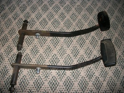
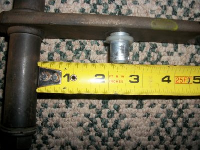
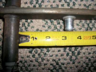
so what your saying is,the only way to get the same mechanical advantage is to get the 3/4" pin location difference with the hydro brake pedal.it's not simply a matter of bringing the hydro unit downward in an attempt to just align the pushrod pin.the leverage point of that extra 3/4" in the pedal pivot is vital?
what if you did both?
Last edited: