More Progress on the 6.9 Rebuild!

hesutton

The Anti-Anderson
Supporting Member
Joined
Aug 19, 2005
Posts
8,200
Reaction score
738
Location
Bowling Green, KY
If you missed the previous posts, they are linked below:
Start Here
Second Update
Third Update
Fourth Update
Fifth Update
Sixth Update

My wife picked up my rebuilt heads on Friday afternoon. By Friday night they were in the shop. I pulled a few of the valves to show off the new stuff on the heads.:D

Three angle grind on valve seats with a 2 degree interference on third angle.
You must be registered for see images

You must be registered for see images


The old worn guides were machined out and new hardend cast iron valve guides where installed. There is such an improvement in the valve to guide clearance now. I fell much better about running these heads.
You must be registered for see images

You must be registered for see images


New intake (Perfect Circle) and exhaust valves (EngineTech).
You must be registered for see images


Perfect Circle intake valve, part number 211-2561. The valve has 0.010 larger margin to save seat replacement.
You must be registered for see images


EngineTech exhaust valve, part number V2307S. They have a Stellite face, recommend for turbo updated IDI engines. The valve has 0.010 larger margin to save seat replacement.
You must be registered for see images


New valve seals with Teflon ring. These are supposed to last much longer with less oil leaking past the seal.
You must be registered for see images

You must be registered for see images


Passenger's side head.
You must be registered for see images


Driver's side head.
You must be registered for see images


More to follow:

Heath
 
Last edited:

PwrSmoke

Full Access Member
Joined
Jan 2, 2007
Posts
807
Reaction score
22
Location
Northwest Ohio
Yes!!

Sutton, my question above that didn't come thru was regarding how much your heads were surfaced. I can see they were. I just wonder how you/they dealt with that. I recently finished overhauling my 6.9L., most of the work being in the heads. My heads needed surfacing due to eroded surfaces (head gasket leakage... 140K miles and 25 years with a Banks kit) and we had to go 0.010" under the min spec (we actually took 0.008 off and oddly, the heads were already at/under min-spec... and I'm the original owner) We carefully set valve protrusion/recession to the spec and I even went so far as to shim one head according to the crushed head gasket dimension, test assemble and check valve-to-piston clearance at full lift (plenty). Needless to say, it got ARP head studs.
 
Last edited:

hesutton

The Anti-Anderson
Supporting Member
Joined
Aug 19, 2005
Posts
8,200
Reaction score
738
Location
Bowling Green, KY
Finally able to post up the rest of the photos.

Well, after the delay with OB being down, I'm going to finish posting up the progress on the 6.9 rebuilt:

The new Victor Rienz head gaskets were next.
You must be registered for see images


Labeled on one side with "UP" so you don't put it on upside down:
You must be registered for see images


The block and heads were throughly cleaned with BrakeKleen. A thin coat of Hylomar was sprayed on the gaskets to help them seal. The Passenger's side was first.
You must be registered for see images

You must be registered for see images


The head was carefully lowered onto the block and the studs were torqued down using the factory sequence to the factory 80 ft/lbs of torque per ARP's recommendations. I used their "Ultra-Torque" fastner lube to ensure the proper torque was applied. Also, I repeated the final line sequence several times until not a single nut moved again.
You must be registered for see images

You must be registered for see images


The Driver's side was next:
You must be registered for see images

You must be registered for see images

You must be registered for see images


Both heads are on and it's looking like a 6.9 again.
You must be registered for see images

You must be registered for see images


More to follow:

Heath
 
Last edited:

hesutton

The Anti-Anderson
Supporting Member
Joined
Aug 19, 2005
Posts
8,200
Reaction score
738
Location
Bowling Green, KY
Once the heads were on..........It was time to test fit the intake manifold. After the decks were milled and the heads resurfaced, I wanted to make sure the intake would fit as it should. It actually fit better after all the machine work was done.
You must be registered for see images


The new valley pan was modified next. This was done to make sure oil draining from the turbo doesn't accumulate in the baffling of the valley pan and cause an oil leak. Obviously, make sure the shavings are out of the pan before installation.LOL
You must be registered for see images


The new Ford lifters were next. They were bathed in oil for a while before installation.
You must be registered for see images

You must be registered for see images

You must be registered for see images


When installing the lifter supports, make sure the little round thingy (LOL) is facing up. The retainer that bolts into the block and holds the lifter supports needs to put pressure on this "bump" in the support.
You must be registered for see images

You must be registered for see images


The push rods were cleaned and inspected. They were then installed. The "bronze" colored side is supposed to go up. But, mine no longer have the bronze color on them. They were installed the same orientation they were removed in.
You must be registered for see images

You must be registered for see images


More to follow:

Heath
 
Last edited:

hesutton

The Anti-Anderson
Supporting Member
Joined
Aug 19, 2005
Posts
8,200
Reaction score
738
Location
Bowling Green, KY
I bought a set of new Melling 7.3 rockers. The Melling part number is MRK-650.
You must be registered for see images


Top
You must be registered for see images


Bottom
You must be registered for see images


The old 6.9 rockers were looking pretty worn and I didn't want to used them again.
You must be registered for see images

You must be registered for see images

You must be registered for see images


After a healthy dose of assembly lube on the new rockers, they were installed on the heads, torque is 20 ft/lbs.
You must be registered for see images

You must be registered for see images

You must be registered for see images


The intake manifold was next. The surfaces on the manifold were prepped as were the intakes on the heads.
You must be registered for see images


The intake was installed using the factory sequence. The torque is 24 ft/lbs. When putting on the valley pan, it is critical to put a healthy bead of quality silicone on the block to valley pan mating surfaces. The rear is so small, it is especially important to get a good seal there, otherwise, you will certainly have a oil leak.
You must be registered for see images


I used the supplied silicone that comes with the Victor Rienz valley pan. It really sealed well the last timed I used it with their valley pan. Again, the rear is harder to get a good seal than the front.
You must be registered for see images


The front is much easier to get a good seal. The surface area is large at the mating surface and there is a hold down bar with four bolts.
You must be registered for see images


That's all for now. I'm going to get the valve covers on next. Then I'll paint the engine and start installing the exhaust manifolds, oil cooler, pullies, and blah, blah, blah.......

Still waiting on my Moose injectors to get finished. My old supposed DPS "turbo calibration" IP:rolleyes: is now a Moose pump.:D

I will get some more stuff posted next week.

Heath
 
Last edited:

hesutton

The Anti-Anderson
Supporting Member
Joined
Aug 19, 2005
Posts
8,200
Reaction score
738
Location
Bowling Green, KY
Yes!!

Sutton, my question above that didn't come thru was regarding how much your heads were surfaced. I can see they were. I just wonder how you/they dealt with that. I recently finished overhauling my 6.9L., most of the work being in the heads. My heads needed surfacing due to eroded surfaces (head gasket leakage... 140K miles and 25 years with a Banks kit) and we had to go 0.010" under the min spec (we actually took 0.008 off and oddly, the heads were already at/under min-spec... and I'm the original owner) We carefully set valve protrusion/recession to the spec and I even went so far as to shim one head according to the crushed head gasket dimension, test assemble and check valve-to-piston clearance at full lift (plenty). Needless to say, it got ARP head studs.

Jim, they were surfaced by the first machine shop I took them to in Evansville, IN. They "couldn't remember" how much they took, but said it was just a few thousands. I had Haas Machine check the thickness of the heads (they have the specs for these IDI's on their computer, which was reassuring). They said they were within spec, and I had about 3-4 thousands to spare.

Heath
 
Last edited:

icanfixall

Official GMM hand model
Joined
Apr 10, 2005
Posts
25,858
Reaction score
673
Location
West coast
The factory thickness of a new head is 4.801. The minimum is 4.785. We still don't know why thid is what the engineers called for because the heads are flat. With proper valve recession in the heads there is no differance in the combustion chamber. You know... The one we don't have..:sly 
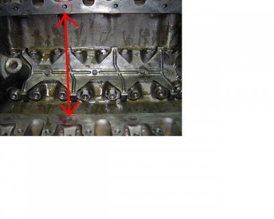
Now milling the block deck will cause the piston to raise up out of the cylinder more but there too we have a spec. Its .031 max. Lower compression pistons are available for the 7.3 and 6.9. Also the top of the piston can be milled some also. Nice work and the pics are outstanding Heath...:hail:thumbsup: Sorry to see the heads do not have plugs in the coolant passages between the head and intake manifold. Thats a bad place for a coolant leak.
 

hesutton

The Anti-Anderson
Supporting Member
Joined
Aug 19, 2005
Posts
8,200
Reaction score
738
Location
Bowling Green, KY
Sorry to see the heads do not have plugs in the coolant passages between the head and intake manifold. Thats a bad place for a coolant leak.

Gary, are you talking about these ports in the attached photo? If so, I don't remember there being any plugs in these before. Even when it was torn down the 1st time.:dunno

Heath
 

Attachments

  • heads.JPG
    heads.JPG
    37.6 KB · Views: 95

icanfixall

Official GMM hand model
Joined
Apr 10, 2005
Posts
25,858
Reaction score
673
Location
West coast
Yes and thats the short answer. The later heads have these ports machined so a freeze plug will press in for a positive seal. Not all 6.9 heads have this machining done to them. I have never seen an intake manifold with coolant passages in it and continue to wonder if there ever was an application for this. I do know the next time my 7.3 comes apart I'm using the 6.9 head gaskets. I have a set here and the 7.3 and the only differance is the lower coolant passage plugged in the 7.3 but open in the 6.9. Why???:dunno Even the 7.3 heads and block have plugs pressed into them to stop coolant flow. If any engine needed more cooling flow its the 7.3. Even a stock 6.9 flows more coolant than any 7.3 turbo or not. There never was a turbo 7.3 head gasket either. So why not allow more coolant flow thru the 7.3 block and heads. Whats the worst thing that can happen... You run too cool and wash the rings down or get poor fuel mileage... all those are easy fixed.
 

Forum statistics

Threads
91,311
Posts
1,130,171
Members
24,121
Latest member
720Diesel

Members online

No members online now.
Top