ok, thanks for extra info fellas, now another question.
I have never replaced a clutch before, so please give me as much detail on this as you like. I will start with my basic knowledge
put in new pilot bushing/bearing
attach flywheel to crank
bolt clutch to the flywheel
put the pressure plate on the back of clutch
and thats all I know. And what does the clutch alignment tool do?
Hank: This is something I wrote up a while back thinking it could possibly be a tech article. It might have some of what you are looking for. Note that Icanfixall's method of supporting the engine is probably better, but the goal of not denting the bottom of the oil pan is the same.
>>>
Here's a few notes on clutch replacement surgery that might be helpful. The patient is a 1988 F350 4x4. This is going to be a SMF (single mass flywheel) conversion using a LUK LFW127 flywheel and a LUK 07-131 pressure plate and disc.
Having done this before, it will not have a gear roll-over noise issue, essentially no sound difference with the clutch in or out while in neutral. The reason for pointing this out is that some SMF clutch discs make a lot of noise, one in particular I tried made gear noise louder then the engine. I believe it's all in how the springs are designed.
Here's how I do it:
Wash the underside of the truck first, then remove the negative terminals on both batteries before beginning.
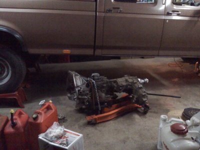
Block the front wheels and jack up the rear end as high as you can go, then put it on jack stands. As you can see in the pic, ramps were slid under the tires for additional safety. Deflate the front tires to about 20 PSI. The point of this is two-fold. The engine and transmission normally slant down at the rear and this will tend to make the crankshaft as parallel to the floor as possible. This makes moving the transmission jack to align the input shaft with the pilot bearing easier. Also, you'll be able to slide the tranny out from under the rear of truck with the extra clearance height.
Shift the tranny into 4th gear and the xfer case in 4W-HI. This will help later because turning the Xfer case input shaft will rotate the tranny input shaft for spline alignment.
Remove the gear shift and 4x4 shifter -- each has two blots, then remove the rubber boots.
Remove the front seat and floor mats.
Remove the transmission sheet metal cover, then remove the top-shifter from the transmission (4 bolts). Duct-tape over the opening to keep dirt out.
Remove the front and rear drive shafts.
Remove the nuts holding the exhaust piping from the exhaust manifolds. Let the exhaust hang down a couple inches so you can remove the clutch inspection cover (4 bolts).
Remove the skid plate under the xfer case.
Because the clutch can be used to jack the crankshaft against the thrust bearing, check the as-found runout on the flywheel now. Mount a dial indicator with a mag-base, dial on the face of the flywheel. Rotate the engine with a 15/16 socket on the engine front vibration dampener, then push in the clutch momentarily to seat the crank against the thrust bearing. Max spec is 0.010 TIR (total indicator reading), <0.005 is nice. If it's out of spec, checking the flywheel itself on a flat surface plate or equivalent will determine whether the problem is the flywheel or the mounting surface on the crankshaft.
Now is a good time to check the travel of the hydraulic slave rod, the nominal travel is 13.5 mm (0.53 inches). If travel is low, the clutch may not disengage fully. Firewall flexing, low fluid, and air in the system are typical causes. The slave on mine has a set screw to bleed the cylinder, but I believe some do not.
Remove the hydraulic clutch slave cylinder, leave the hydraulic line attached. Assuming the plastic retaining tabs are intact, push on the clutch fork to force the slave cylinder piston rod into the cylinder and attach the plastic tabs. Use a screw driver to bend the metal retainers away from the bell housing a bit, and take the cylinder off at an angle that leaves the rod in the clutch fork until the cylinder clears the bell housing. Rotate the slave cylinder 180 degrees on it's hydraulic line, then tuck it away behind a convenient brake line to get it out of the way. NOTE: Attaching the clutch slave cylinder is similarly awkward, place the plastic cup with the rod into the fork at an angle, then push it onto the bell housing until the metal clips snap over the mount, then push on the clutch fork to force the slave cylinder piston rod into the cylinder to un-attach the plastic tabs.
Disconnect the electrical connections on the tranny and xfer case.
Remove the speedo gear/cable from the transmission. Bag the speedo gear and plug the hole to keep dirt out.
Place the transmission jack as rearward as possible without hitting the crossmember. It will be tail heavy with the xfer case on, so chain and strap it on the forward side of the top-shifter mount.
Safety note: The tranny and xfer case weigh a lot, and can crush you. The xfer case moves the center of gravity to the left, and to compensate, the left caster wheel on the pictured jack is moved further outboard. Some mechanics will separate the two components, it all depends on what type of jack you have and their weight capacities. In any case, strap and chain it securely to the transmission jack with some wood cribbing between the transmission and the floor of the jack to keep it from rotating.
Remove the two nuts holding the transmission mount to the cross brace, raise the jack until the mount lifts off the cross brace, then remove it.
Lower the transmission jack until you can get a socket on the top two bolts holding the bell housing to the engine.
Place a hydraulic bottle jack under the rear most part of the engine oil pan to support the engine after transmission separation. A piece of thick rubber gasket material between the bottle jack and the pan works nice to spread the load. Raise the bottle jack so it just lifts the engine slightly, and is supporting it. This should be a good bottle jack that you know doesn't leak down because it's going to be here until re-assembly.
Remove the 6 bolts holding the bell housing to the engine - the 2 on the top are shorter.
Gently slide the transmission jack to the rear, and when the input shaft clears the clutch, lower it down.
Remove the 6 bolts holding the pressure plate to the flywheel evenly -- leave a top one for the last one removed and be prepared for gravity. Remove the pressure plate and disc.
Remove the 9 bolts holding the flywheel to the crankshaft -- leave a top one in for the last one removed and be prepared for gravity. Remove the flywheel.
Check for rear main and transmission input seal leaks.
Clean the bolt holes in the crankshaft -- they are through holes, so don't blow out the holes. Suggest using and old bolt with a couple of flutes ground in using a bench grinder.
Remove the clutch fork and release bearing. Always use a new release bearing, and consider a new clutch fork if it's worn.
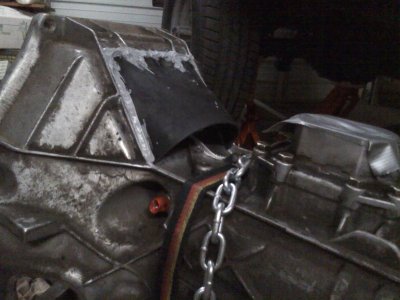
In one of the pics you'll notice a custom rubber shroud over the top air vents in the bell housing. It keeps the fuel, oil, coolant or whatever out. It's easy to make and it's attached with silicone gasket maker
Clean the mating surface for the flywheel to the crankshaft, remove any dings with a flat stone or similar. Any protrusions or dirt here will tend to cause the face of the flywheel to run-out, and the effect is magnified by the relatively large outside diameter of the flywheel compared to the diameter where it attaches to the crankshaft.
If the flywheel surface looks good and the runout was acceptable, I usually just clean up the surface with some wet/dry paper on a ground-flat sanding block. Otherwise, re-surfacing is advisable. Whatever method of re-surfacing is used, the end result should be that the face of the flywheel is parallel to the crankshaft mounting surface. To check this: Use a large flat surface with a good finish (surface plate, mill table, even a good drill press table). Grease up the mounting surface of the flywheel and place it on the flat surface. Place a dial indicator on the edge of the flywheel's friction surface and slowly turn the flywheel. I prefer less then 0.003 TIR in this test because it will probably be a bit more after mounting to the crankshaft (Murphy's law). There's more flatness checks that can be done with a surface plate or mill table, and if you have access to these you likely know what to do.
In the pic you'll see my son re-finishing this flywheel on a rotary table in a milling machine. After machining, it's block sanded to improve the finish a bit. The face run-out and all around flatness was 0.001 using a surface plate and dial indicator.
Press a new pilot bearing into the flywheel. I used the standard roller bearing style, there is a plastic/kevlar style available as well.
Clean and check the mounting surfaces of the bell housing and engine plate. Any protrusions or gunk on these surfaces will effect the pilot bearing and input shaft alignment.
Mount the flywheel to the crankshaft, don't forget the 10-hole washer plate and adding sealer to the threads if the bolts are not already pre-coated. The torque is 50 FT-LBS.
Right now is a good time to check the flywheel face runout, except that the crankshaft needs to be forced against it's thrust bearing with a prybar before each dial indicator reading. Because the flywheel has been checked on a flat surface plate and the mounting surfaces are cleaned up, I usually just wait and do a final check when it's easier to use the clutch slave cylinder to jack the crankshaft against the thrust (same as before).
The surface of the input shaft tube where the release bearing slides may need some touch up with some wet/dry paper for a good finish. Also inspect the end of the input shaft that goes into the pilot bearing and polish as necessary.
Apply a very small mount of high temp grease to the transmission input splines, then slide the clutch disc on and off. Remove all the excess grease, repeat until there is no excess grease -- just a fine film.
Apply some high temp grease to the inside of the release bearing, the clutch fork pivot, and to where the fork contacts the back of the release bearing. Install the release bearing and clutch fork.
Install the pressure plate and clutch disc using the alignment tool to center everything. If the alignment tool fit is loose, compensate by lifting the disc slightly. The torque on the pressure plate bolts is 20 FT-LBS and I prefer blue locktite or similar on these.
Rotate the crankshaft so that the clutch disc splines are lined up vertical -- hang something on a string to act as a plumb-bob to sight against. Now rotate the tranny input shaft until it's splines are similarly vertical (sight against a rib in the bell housing). Note the position of the output shaft of the transfer case for reference. All this pre-positioning is going to take the guesswork out of whether the splines are aligned.
Install the transmission. From the bottom, sight up the bell housing, using the flywheel as a reference to get them parallel. Use a tape measure to keep the gap between the left and right sides of the bell housing and engine equal. To tell if the splines have mated, try to turn the xfer case output shaft.
At this point, assembly is essentially the reverse of disassembly, so there's no point of repeating the above.
Best of luck, hope this was helpful.


 Lifting from the back is far easier than lifting from the front. The motor is almost exactly lined up for the trans. I lifted from the front and it was hell. No matter what I did it was wrong. When I finally got the truck frame highe enough for the trans sitting on the jack to slip under the truck the motor was too high. I had to drop the truck so the trans would match up. BTR installs trans from the rear lift just like we should do. Laying on our backs. Also support the motor from the oil pan rail only. Not from the bottom or you will dent the pan into the oil pickup screen. That will kill the motor. Jack up the motor from one side of the oil pan rail. Then place a cut 2x4 from the ground up to the other pan rail. drop the jack and its set... It can't fall off either just as long as the truck does not roll away.