You must be registered for see images attach
here you go
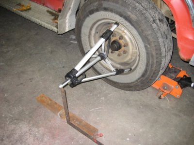
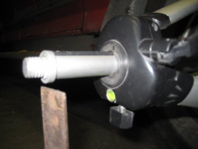
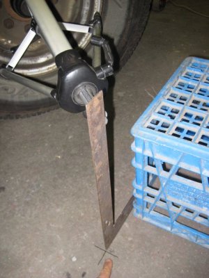
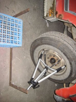
And a pervious post is incorrect you get speed woobles from lack of caster not to much. excessive caster causes hard stering at slow speeds . and if you must do this at home buy a caster guage from harbor freight it cannot be done with levels
P.S. sorry for delay was at baseball game
Not looking for an argument but my previous post concerning steering wobble upon hitting bumps due to excessive positive caster is not incorrect. Most recently Ford published a TSB concerning this very phenomenon in later models F250, 350, 450 and 550's. The same mechanics apply to any vehicle. Ford calls it steering oscillation, we call it the death shake. It is quite severe. Here is the copy of the TSB. You will see that it supports my statement.
TSB
07-10-10 STEERING WHEEL OSCILLATION
Publication Date: May 10, 2007
FORD: 2005-2007 F-Super Duty
This article supersedes TSB 07-5-7 to update the Parts.
ISSUE:
Some 2005-2007 F-Super Duty vehicles may exhibit steering wheel oscillation (back and forth motion), immediately following front or rear wheel impacts (i.e. pavement joints, frost heaves, rough roads, etc.). Steering wheel motion is typically in the range of ± 5 degrees, and typically dampens out in fewer than five oscillations. This condition occurs mostly on F-250/F-350 4X4 vehicles, and is more evident on trucks equipped with a gas engine.
ACTION:
Refer to the following Service Procedure to minimize the steering wheel oscillations on impacts, however, there may be some remaining minor oscillation which would be considered normal.
SERVICE PROCEDURE SUMMARY
Set tire pressure and road test vehicle to evaluate vehicle before proceeding with further repairs. If issue is resolved, do not proceed with the rest of this TSB.
If concern still exists, install a new steering damper (frame-mounted bracket and steering damper assembly on F-250/F-350 4X4 applications only). For F-250/F-350 4X2 and all F-450/F-550 applications, inspect damper for leaks and replace if necessary, torque steering and suspension fasteners per Workshop Manual (WSM).
If concern still exists, check front alignment and reduce front caster.
Replace redundant control steering wheel (if equipped and vehicle built prior to 10/8/2004).
VEHICLE INSPECTION - TIRE PRESSURE
Set tire pressures as indicated on the vehicle label (located on driver's door label).
NOTE: SETTING TIRE PRESSURE TO DOOR SPECIFICATION IS ONE OF THE SINGLE MOST IMPORTANT MEASURES IN RESOLVING THIS ISSUE. LOWERING TIRE PRESSURE WILL MAKE THIS ISSUE WORSE.
ROAD TEST
Ask customer what type of road surface and speed generates the steering wheel oscillation.
Road test vehicle on similar road surface and speed, to gain a feel for the customer's issue.
If no issues are identified during the road test, do not proceed with the rest of this TSB.
STEERING DAMPER INSPECTION/REPLACEMENT AND STEERING/SUSPENSION FASTENER TORQUE CHECK
F-250/F-350 4X4 Applications:
Remove existing steering damper and frame attachment bracket.
Replace steering damper and frame mounting bracket with steering damper and frame bracket.
Attach steering damper to frame bracket and torque bolt to 76 lb-ft (103 N-m).
Assemble bracket and shock assembly to the frame with attachment bolt retainer pointing to rear of vehicle. Torque frame bracket nuts to 59 lb-ft (80 N-m).
Attach other end of shock to the steering drag link and torque to 66 lb-ft (90 N-m).
Install damper bolt cap to assure a friendly surface for the battery cable in case of casual contact.
NOTE: CHECK SURROUNDING ENVIRONMENT TO THE FRAME BRACKET AND DAMPER ASSEMBLY TO ENSURE THAT BATTERY CABLES ARE NOT CONTACTING BRACKET/BOLTS/DAMPER. ALSO, VERIFY THAT TRANSMISSION OIL COOLER LINES HAVE CLEARANCE TO THE DAMPER DUST SHIELD.
F-250/F-350 4X2 And All F-450/F-550 Applications:
Wipe down and inspect the steering damper. Turn the steering wheel from lock to lock several times to cycle the steering damper and inspect for leaks.
If leaks are present, install a new steering damper.
Steering/Suspension Fastener Torque Check (4X2 And 4X4)
Check torques on the following steering and suspension fasteners and adjust to specification as required (see following Table).
Torque Specification
Description Lb-ft Nm
Damper nuts (F-250/F-350 4X2) 59 80
Damper-to-bracket (F-250/ F-350 4X4) 76 103
Damper-to-drag link 66 90
Drag link-to-pitman arm nut 129 175
Inner tie-rod end nuts 85 115
Outer tie-rod end nuts 85 115
Track bar bracket-to-frame nuts and bolts 129 175
Track bar-to-track bar bracket bolt 406 550
Track bar-to-axle nut 185 250
Radius arm-to-axle bolts 222 300
Radius arm-to-bracket nut 222 300
NOTE: ADJUSTING TORQUE ON STEERING AND SUSPENSION FASTENERS IS VERY IMPORTANT IN RESOLVING THIS ISSUE. FASTENERS THAT ARE IMPROPERLY TORQUED WILL MAKE THIS ISSUE WORSE.
FRONT WHEEL ALIGNMENT AND REDUCE FRONT CASTER
NOTE: OSCILLATION ISSUES RESOLVED BY WHEEL ALIGNMENT ARE WARRANTED FOR 12/12 ONLY, REGARDLESS OF OTHER STEPS PERFORMED.
Measure wheel alignment. Verify that front caster, camber, and total toe are within specification. Adjust as required. Refer to the WSM, Section 204-00 for complete alignment specifications.
REDUCE FRONT CASTER
Note the current front caster.
Use alignment adjustment bushings to reduce front caster by 0.5 to 0.75 degrees. The caster setting may be at the lower end of the specification as long as the vehicle drives smoothly. Do not put caster setting below the lower specification limit. Use alignment adjustment bushings.
F-250/350 4X4:
5C3Z-3B440-CCC (0.5 degree bushing)
5C3Z-3B440-DDD (0.75 degree bushing)
5C3Z-3B440-EEE (1.0 degree bushing)
F-450/550 4X4 and 4X2:
5C3Z-3B440-HHH (0.5 degree bushing)
5C3Z-3B440-JJJ (0.75 degree bushing)
5C3Z-3B440-*** (1.0 degree bushing)
F-250/350 4X2:
5C3Z-3B440-C (0.5 degree busing)
5C3Z-3B440-D (0.75 degree bushing)
5C3Z-3B440-E (1.0 degree bushing)
For All 4X4 and for F-450/550 4X2:
Rotate the alignment adjustment bushing so that the bushing hole is in the 45 degree forward and inboard position. (See Figure 1)
Figure 1 - Article 07-10-10
This should lower the caster, while keeping the camber within the specification range. If the camber is not in the specification range than rotate the alignment adjustment bushing as needed.
The final caster and camber settings must be within the specification limits.
Maintain the current front camber, cross-camber and cross-caster settings as close as you possibly can.
Adding weight behind the rear axle lowers the rear of the vehicle, which decreases the frame angle, which in effect increases caster.
For All F-250/350 4X2:
Observe the camber position of the alignment bushing that is currently in the truck and attempt to maintain that position while moving the caster position forward in the truck.
The final caster and camber settings must be within the specification limits.
NOTE: CASTER SETTING IS VERY IMPORTANT IN RESOLVING THIS ISSUE. INCREASING THE CASTER SETTING WILL MAKE THIS ISSUE WORSE.
REPLACEMENT OF REDUNDANT CONTROL STEERING WHEEL - Vehicles Built Prior To 10/8/2004 Only
NOTE: THE REPLACEMENT STEERING WHEEL WILL CONTAIN THE REDUNDANT CONTROLS.
Remove driver air bag assembly. Refer to WSM, Section 211-04 for complete instructions.
Remove the steering wheel.
Install new steering wheel.
Reinstall driver air bag assembly.
Re-set clear vision as required.
NOTE: FOR ADDITIONAL INFORMATION, PLEASE REFER TO SECTION 211-04 OF THE WSM FOR COMPLETE REMOVAL AND INSTALLATION PROCEDURES FOR THE STEERING COLUMN.
PART NUMBER PART NAME
5C7Z-3600-ABA Redundant Control Steering Wheel Asy (King Ranch Tan/Peb)
5C7Z-3600-CBA Redundant Control Steering Wheel Asy (Charcoal Black)
5C3Z-3B440-C F-250/350 4X2 (0.5 degree bushing)
5C3Z-3B440-D F-250/350 4X2 (0.75 degree bushing)
5C3Z-3B440-E F-250/350 4X2 (1.0 degree bushing)
5C3Z-3B440-CCC F-250/350 4X4 (0.5 degree bushing)
5C3Z-3B440-DDD F-250/350 4X4 (0.75 degree bushing)
5C3Z-3B440-EEE F-250/350 4X4 (1.0 degree bushing)
5C3Z-3B440-HHH F-450/550 4X4 and 4X2 (0.5 degree bushing)
5C3Z-3B440-JJJ F-450/550 4X4 and 4X2 (0.75 degree bushing)
5C3Z-3B440-*** F-450/550 4x4 and 4x2 (1.0 degree bushing)
W520117-S441 Nut - Hex - RH Thread
W706196-S439 Bolt
7C3Z-3E652-C Bracket
5C3Z-3E651-B Steering Damper (F-250/F-350 4X2)
8C3Z-3E651-C Steering Damper (F-250/F-350 4X4)
5C3Z-3E651-D Steering Damper (F-450/F-550)
W711570-S300 Bolt Cap
NOTE: LABOR OPERATIONS IN THIS TSB CAN BE CLAIMED TOGETHER.
NOTE: OSCILLATION ISSUES RESOLVED BY WHEEL ALIGNMENT ARE WARRANTED FOR 12/12 ONLY, REGARDLESS OF OTHER STEPS PERFORMED.
WARRANTY STATUS:
Eligible Under Provisions Of New Vehicle Limited Warranty Coverage
IMPORTANT: Warranty coverage limits/policies are not altered by a TSB. Warranty coverage limits are determined by the identified causal part.
OPERATION DESCRIPTION TIME
071010A 2005-2007 F-Super Duty: Check Tire Pressure, Road Test To Verify Repair, Concern Resolved, Return To Customer (Do Not Use With 1007D, 3001A, 3001A1, 3001A6, 3600A) 0.4 Hr.
071010B 2005-2007 F-Super Duty: Check Tire Pressure, Road Test To Verify Repair, Concern Not Resolved, Check Steering Damper Replace If Necessary, Verify Proper Torque On Steering Components, Road Test If Concern Is Resolved Return To Customer (Do Not Use With 1007D, 3001A, 3001A1, 3001A6, 3600A) 1.4 Hrs.
071010C 2005-2007 F-Super Duty 250/350 4X2 DUAL REAR WHEEL: Check And Adjust Front Wheel Alignment, This Labor Operation Can Be Claimed With Operation B Only (Do Not Use With 1007D, 3001A, 3001A1, 3001A6, 3600A) 1.9 Hrs.
071010C 2005-2007 F-Super Duty 250/350 4X2 SINGLE REAR WHEEL: Check And Adjust Front Wheel Alignment, This Labor Operation Can Be Claimed With Operation B Only (Do Not Use With 1007D, 3001A, 3001A1, 3001A6, 3600A) 1.5 Hrs.
071010C 2005-2007 F-Super Duty 250/350 4X4 SINGLE REAR WHEEL: Check And Adjust Front Wheel Alignment, This Labor Operation Can Be Claimed With Operation B Only (Do Not Use With 1007D, 3001A, 3001A1, 3001A6, 3600A) 1.8 Hrs.
071010C 2005-2007 F-Super Duty 250/350 4X4 DUAL REAR WHEEL: Check And Adjust Front Wheel Alignment, This Labor Operation Can Be Claimed With Operation B Only (Do Not Use With 1007D, 3001A, 3001A1, 3001A6, 3600A) 2.1 Hrs.
071010C 2005-2007 F-Super Duty F450/550 4X2/4X4 DUAL REAR WHEEL: Check And Adjust Front Wheel Alignment, This Labor Operation Can Be Claimed With Operation B Only (Do Not Use With 1007D, 3001A, 3001A1, 3001A6, 3600A) 2.3 Hrs.
071010D 2005-2007 F-Super Duty With Redundant Steering Control Built Prior To 10-8-2004: Replace Steering Wheel, Includes Time To Depower And Repower The Supplemental Restraints System Can Be Claimed With Operation A Or B (Do Not Use With 1007D, 3001A, 3001A1, 3001A6, 3600A) 0.7 Hr
DEALER CODING
BASIC PART NO. CONDITION CODE
(Operation A) NPF 82
(Operation B) 3E651 42
(Operation C) FRONT W6
(Operation D) 3600 42
--------------------------------------------------------------------------------
NOTE: The information in Technical Service Bulletins is intended for use by trained, professional technicians with the knowledge, tools, and equipment to do the job properly and safely. It informs these technicians of conditions that may occur on some vehicles, or provides information that could assist in proper vehicle service. The procedures should not be performed by "do-it-yourselfers". Do not assume that a condition described affects your car or truck. Contact a Ford, Lincoln, or Mercury dealership to determine whether the Bulletin applies to your vehicle. Warranty Policy and Extended Service Plan documentation determine Warranty and/or Extended Service Plan coverage unless stated otherwise in the TSB article. The information in this Technical Service Bulletin (TSB) was current at the time of printing. Ford Motor Company reserves the right to supercede this information with updates. The most recent information is available through Ford Motor Company's on-line technical resources.
Copyright © 2007 Ford Motor Company
 would drive circles around the 80's model twin I beams so far as the ability to provide superior handling and a pleasurable stable drive. Cranking the caster up can help the steering return but you have to be careful because it can also increase the probabilty of shimmy after hitting bumps. Think of how your caster angle can effect your wheels this way. Think of those annoying wheels on your shopping cart. Ever get one that wobbles like crazy, pulls left or right can't hardly turn it when it's full? Same principle. I am sorry to say that I have pretty much exhausted my arsenal of ideas and I'm scratching my head. There's only so much you can do without actually being able to drive the truck and see it. You need a good Alignment shop to make the next step. I wish you were here I'd line it up for you. Want to take a trip to Albuquerque?
 . Thanks for the thought though.