I can't imagine the location of the injectors would be consistent enough for this to work. Locations would probably change just by changing injectors.
You are using an out of date browser. It may not display this or other websites correctly.
You should upgrade or use an alternative browser.
You should upgrade or use an alternative browser.
SPINOFF: Aluminum injector return rail.
- Thread starter 04_6.0
- Start date
FordGuy100
Registered User
Yes this is brainstorming phase. I'll hopefully get the design done tomorrow and cut this weekend or next hopefully before Christmas.
Only thing is we can not do our return lines like a cummins engine. The injector is held in place by a outside nut on the injector allowing the injector to be aligned the correct way then torque the hold down nut to spec. Attach the return lines and your done. Our injectors are not aligned the same exact way on every injector. I know on mine I have some return hole that are 60-90 degrees off from one another.
I too am skeptical about the manifold but I am willing to make a few sets and give it a try. I want to make an internal groove to hold the orings in place.
Your right on that part.
I can't imagine the location of the injectors would be consistent enough for this to work. Locations would probably change just by changing injectors.
If they were to make the lines/caps a solid piece, you could just clip it onto all of the injectors at once (on each side). The only place to leak would be the o-ring/cap area.
I like the idea of the orings tightened in compression. Look up Cajon fittings (I think they call them ultra-torr now that swagelok owns them). If they will hold high vacuum, it should work for a low pressure return line. It might be worth looking at engineering the parts so that they accept a larger cord thickness oring, maybe a -211 instead of -111. Not sure what the ID and OD of that dash number is but hopefully you get the idea.
Something to think about. Why stop at the return cap? Why not change the pressure line connections to be part of the solution?
Sent from my iPhone using Tapatalk
Something to think about. Why stop at the return cap? Why not change the pressure line connections to be part of the solution?
Sent from my iPhone using Tapatalk
Close[B]Just remember, there is only about 0.020 squeeze, 0.010 to a side on the o'rings, so the center to center of the caps with a manifold would have to be damn close, not more than +/- 0.003 CC, minimum squeeze is 0.007 for a seal. Then you'd have to take into account the tolerance of manufacturing of the heads and injectors. Just something to think about.
[/B]
should double the +/- 0.003cc as one injector could be +0.003 the other -0.003. So the 0.010 squish would now be .0004.
04_6.0
Full Access Member
I forgot some dimensions on the injector, the distance between the oring center to center. The gap and depth of the oring groove.
Well i must say that i am rather impressed with the tolerances held by IH when building this engine. Measured both drivers and passenger heads and got the measurements that i need furthest one was .003 and that was from injector to injector between the cylinders. Ive got the design laid out and the model done. Ill make some fab drawings at lunch. i know it doesnt look like much but there is a lot going on in there. 1/4" return rail on the inside. Ends will be tapped
Well i must say that i am rather impressed with the tolerances held by IH when building this engine. Measured both drivers and passenger heads and got the measurements that i need furthest one was .003 and that was from injector to injector between the cylinders. Ive got the design laid out and the model done. Ill make some fab drawings at lunch. i know it doesnt look like much but there is a lot going on in there. 1/4" return rail on the inside. Ends will be tapped
You must be registered for see images attach
You must be registered for see images attach
Close
should double the +/- 0.003cc as one injector could be +0.003 the other -0.003. So the 0.010 squish would now be .0004.
That, is exactly what I was trying to portray. (Correction:.0.004 not 0.0004)
There is no way that a solid manifold will work leak free. These engines have already been manufactured holding close tolerances. Now if they could be made holding tolerances in the tens of thousands, and injectors held to that tolerance, then a manifold might work. Yeah, I know some components are made holding tolerances in the tens of thousands, I'm referring to the heads and injectors only. I wouldn't doubt the injectors are made with under a +/- 0.001 tolerance, but heads, no, there was/is no reason to do that.
Think think, How are you going to maintain the squeeze factor with an internal groove. To hold a 0.010 squeeze 10 on each side, you have to have a 0.040 squeeze on initial installation. Try it, might work. Just to grind the tool for a concave groove and find location is going to be a challange.I too am skeptical about the manifold but I am willing to make a few sets and give it a try. I want to make an internal groove to hold the orings in place.
Edit: Whoops, your the guy with the CNC machine, might be able too.
I'm with those that think a solid manifold is not the way to go. Figuring a way to hold the caps in place, keeping a good squeeze on the o rings that wont be disturbed by changing hoses between is the way to go.
redneckaggie
rebel w/o a cause
Honestly I have not had many problems with the return lines in my truck. I dont think that the rail will work just simply because the tolerances will add up way to quickly and you may have it work on one set of heads because they stack in your favor and not the next. I would much rather have a solid stainless or aluminum cap with npt threads on either side. This way if someone wanted to use the factory hose barb design they could, if they want to use an line they can, gives you the most flexibility while retaining reusable caps. Also gives people the flexibility to reroute the returns however they would like with npt 90s or plugs.
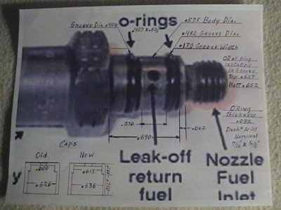
So Here is some of the measurements and pic with measurements on injector and o'ring, caps in lower left corner.
I measured six (6) different injectors, 2 were made in Italy, other 4 by Delphi. There wasn't a half thousandth diference between them. tolorances were held close.
All measurements were taken with a Digital Caliper. Some measurements where + 0.0005, I discarded that.
The Old cap, still with Gray paint on it yet from a 1990 IH.
New Cap was made in Germany, with IH part # 180557 I think.
You can see the O'ring groove depths are not alike, the bottom groove Od is .459 and top groove is .432, so actually there is a stretch of the bottom O'ring of .027.
I could lay a ring flat and then try to pick it up with the cap over it, some caps, would some wouldn't, that was out of 4 old would and 4 new wouldn't.
Draw your own conclusions from this. NO, the caps are NOT to scale. Gonna post this over in ADV's thread also.
I measured six (6) different injectors, 2 were made in Italy, other 4 by Delphi. There wasn't a half thousandth diference between them. tolorances were held close.
All measurements were taken with a Digital Caliper. Some measurements where + 0.0005, I discarded that.
The Old cap, still with Gray paint on it yet from a 1990 IH.
New Cap was made in Germany, with IH part # 180557 I think.
You can see the O'ring groove depths are not alike, the bottom groove Od is .459 and top groove is .432, so actually there is a stretch of the bottom O'ring of .027.
I could lay a ring flat and then try to pick it up with the cap over it, some caps, would some wouldn't, that was out of 4 old would and 4 new wouldn't.
Draw your own conclusions from this. NO, the caps are NOT to scale.
Gonna post this over in ADV's thread also.Attachments
Last edited:
04_6.0
Full Access Member
Lots of good ideas and thank you for the measurements oldbull.
Ok so I am fairly confident in saying that the rail will not work. I had two friends come over and i took measurements on their motors. I had dimension that were .037 out from mine. So what would be the next best thing to do? Caps like ADV? I dont think AN fittings will work on the caps. If the lines that connects the injector are not the same length it will push or pull the cap causing it to leak....suggestions/comments welcome???
Ok so I am fairly confident in saying that the rail will not work. I had two friends come over and i took measurements on their motors. I had dimension that were .037 out from mine. So what would be the next best thing to do? Caps like ADV? I dont think AN fittings will work on the caps. If the lines that connects the injector are not the same length it will push or pull the cap causing it to leak....suggestions/comments welcome???
Last edited:
smolkin
Stuck inside Mobile
Let me start by confessing that I have no knowledge of commonly available materials for milling or fabrication; however, couldn't you use Al pipe stock if it was available in the correct inside diameter? Purely for example, I found this which has an ID of .622". I'm envisioning a jig to crimp in the top to create the lip, and you could use threaded nipples into tapped holes for the return lines. Just a thought. Something like this might be easier if you don't have access to a fully equipped metal shop (I don't either).
(e: Should have pointed out this would be for replacement caps like the OEM, not a rail)
(e: Should have pointed out this would be for replacement caps like the OEM, not a rail)
Last edited:
jaluhn83
Full Access Member
This may be a dumb question, but do people really have *that* much trouble with the return lines??? Sure they get old and break eventually and can cause air leaks, but it's not something that happens overnight, nor is it particularly hard to replace them.
I think the work and cost involved in making a solid manifold is going to far and away outweigh the benefit, assuming it even works reliably - my bet would be that it would be quite difficult to get it accurate enough to seal properly and would probably wind up matched to each engine / injector set.
If you're that concerned about it just weld a fitting onto the injector body and use some sort of positive seal hose between them.
04_6.0
Full Access Member
Correct after measuring the heads and position of the injectors a solid tail will not work. I think it would work but it would have to be on an indivfual truck basis.
redneckaggie
rebel w/o a cause
I hate to be the bearer of bad news but calipers are hardly accurate to the .001 much less .0005. I believe the mitutoyo calipers in our shop come with papers saying that they are accurate within .003. The brown and sharpe that we order for our critical machinists claim to be accurate to +-.001
Similar threads
- Replies
- 5
- Views
- 899
- Replies
- 54
- Views
- 5K
- Replies
- 2
- Views
- 765