This really should be in the PSD forum.
Maybe you can use some of this info to troubleshoot the ICP.
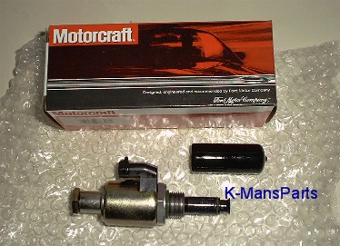
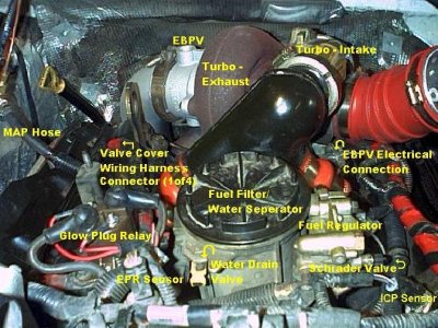
ICP: Injection Control Pressure sensor
Feedback input; The PCM monitors the high pressure oil system to determine if it needs to be
increased if load demand increases. It also uses this to stabilize idle speed. volts in,
1.0volt@580psi, 3.22volts@2520psi. PID: ICP (pressure), ICP V (voltage)
ICP--Injection Control Pressure--and RPM--CaMshaft Position Sensor: After 3 minutes at 3300
RPM, ICP pressure should be below 1400psi for Federal, 1250psi for California Emmisions,
and 1500psi for 99.5. At idle, ICP should be 550-700psi for Federal, 400-600 for California
and stable.
ICP--Injection Control Pressure--IPR--Injection Pressure Regulator--and MFDES--Mass Fuel
Desired: ICP should rise as IPR duty cyle increases; MFDES and IPR should rise at the same
rate as load and/or demand increases (actual readings may not match); ie. ICP=500psi,
IPR=12%, MFDES=10MG @500 RPM; ICP=900psi, IPR=22%, MFDES=20MG
@1800RPM/cruise; ICP=1800psi, IPR=50%, MFDES=40MG @3000RPM/hard accel.
ICP--Injection Control Pressure--and ICP V--ICP Voltage: ICP should read 0psi, ICP V should
read 0.20-0.25 volts, Key On Engine Off.
AP: Accelerator Pedal position sensor
Load/demand input; PCM uses this to determine mass fuel desired, adjusts fuel delivery
through IPR duty cycle and fuel pulse width and injection timing; 5 volts in, 0.5-0.7 volts at idle,
4.5 volts at WOT. PID: AP
IVS:Idle Validation Switch
Strategy input; On-off switch that the PCM uses to identify required operating mode; idle or
power. 0 volts at idle, 12 volts off idle. PID: IVS (off/on)
IPR: Injection Pressure Regulator
Output; The PCM controls the high pressure oil system by varying the duty cycle of the IPR.
The IPR controls the oil bypass circuit of the high pressure pump. 0%=full return to sump
(open valve), 100%=full flow to injectors (closed valve). The PCM monitors the system with the
ICP input. The PCM can control fuel delivery to the injectors by increasing the IPR duty cycle
which increases fule pressure through the injector nozzels. PID: IPR (% of duty cycle), MFDES
Mass Fuel Desired an internal PCM calculation based on load demand (MG)
Check this also.
....It recieves a 5 volt reference on the Brown/White ---- ground circuit on the Black/White wire. It also sends a .9 volt to 4.5 volt signal on the Green/White wire to the PCM to indicate throttle position.
The IVS is a normally closed switch. It has 2 wires, 1 is a Brown, a fused battery voltage wire , the other is Red/Orange and goes to the PCM to confirm pedal position. When the pedal is in the idle position the Brown wire at the IVS is battery voltage and the Red/Orange wire is 0 volts.
As pedal travel
increases to approximately 1.3 volts as indicated on the Green/White wire at the AP sensor[or TPS], the voltage on the Red/Orange wire should increase to battery voltage to indicate acceleration.

 darn dogs