Scott,
I have this for the OBS 7.3 DI
1994-96 7.3L DI Turbo Diesel Engine
RIGHT CYLINDER HEAD
See Figures 10, 11, 12, 13, 14, 15 and 16
Fig. 10: Remove the oil rail drain plug as shown-7.3L DI turbo diesel engine
Fig. 11: Remove the injector using special tools as shown-7.3L DI turbo diesel engine
Fig. 12: Special fuel injector protection sleeve and holding rack-7.3L DI turbo diesel engine
Fig. 13: Install a lifting eye as shown
Fig. 14: Use a suitable bore brush to clean out the injector bores
Fig. 15: Cylinder head bolt tightening sequence-7.3L DI turbo diesel engine
Fig. 16: Install the injectors using the special tool as shown-7.3L DI turbo diesel engine
Disconnect both negative battery cables.
Drain the cooling system.
Remove the radiator.
Remove the turbocharger assembly.
Disconnect the fuel lines by disconnecting them from the rear of both cylinder heads and the fuel pump.
Label and disconnect the wiring from the alternator.
Remove the adjusting bolts and pivot bolts from the alternator and the vacuum pump and remove both units.
Remove the alternator and its bracket.
Remove the engine oil dipstick tube.
Remove the MAP sensor and position it aside.
Remove the valve cover
Remove the connectors from the injectors and glow plugs.
Remove the valve cover gasket.
Remove the high pressure oil pump supply line to the right cylinder head.
Remove the exhaust back pressure line.
Remove the three glow plug relay bracket nuts and the ground wire.
Disconnect the heater hose from the cylinder head.
Remove the outer half of the heater distribution box.
Remove the four outboard fuel injector hold-down bolts, retaining screws and four oil deflectors.
WARNING
Remove the oil drain plugs prior to removing the injectors or oil could enter the combustion chamber which could result in hydrostatic lock and severe engine damage.
Remove the oil rail drain plugs.
Remove the fuel injectors using Injector Remover No. T94T-9000-AH1, or equivalent. Position the tool's fulcrum beneath the fuel injector hold-down plate and over the edge of the cylinder head. Install the remover screw in the threaded hole of the fuel injector plate (see illustration). Tighten the screw to lift out the injector from its bore. Place the injector in a suitable protective sleeve such as Rotunda Injector Protective Sleeve, No. 014-00933-2, and set the injector in a suitable holding rack.
Use a suitable vacuum tool, such as Rotunda Vacuum Pump, No. 021-00037, or equivalent to remove the oil and fuel left over in the injector bores.
Remove the rocker arms and pushrods, KEEP EVERYTHING IN ORDER.
Remove the four glow plugs.
Remove the right turbo exhaust inlet pipe.
Remove the ground strap from the rear of the cylinder head.
Disconnect the fuel return line at the front of the cylinder head.
Remove the four inboard fuel injector shoulder bolts.
Remove the cylinder head bolts and attach a Rotunda Cylinder Head Lifting Bracket, 014-00932-2, or equivalent.
Carefully lift the cylinder head out of the engine compartment and remove the head gaskets.
To install:
To prepare a good seat for the fuel injector O-rings, use a suitable injector sleeve brush to clean any debris from the bore.
Carefully clean the cylinder block and head mating surfaces.
Position the cylinder head gasket on the engine block and carefully lower the cylinder head in place.
Install the cylinder head bolt and torque in 3 steps using the sequence shown in the illustration.
Lubricate the threads and the mating surfaces of the bolt heads and washers with engine oil.
Connect the fuel return line to the cylinder head.
Install the four inboard injector shoulder bolts. Tighten them to 9 ft. lbs. (12 Nm).
Install the fuel injectors using special tools as follows:
Lubricate the injectors with clean engine oil. Using new copper washers, carefully push the injectors square into the bore using hand pressure only to seat the O-rings.
Position the open end of Injector Replacer, No. T94T-9000-AH2, or equivalent between the fuel injector body and injector hold-down plate, while positioning the opposite end of the tool over the edge of the cylinder head.
Align the hole in the tool with the threaded hole in the cylinder head and install the bolt from the tool kit. Tighten the bolt to fully seat the injector, then remove the bolt and tool.
Install the four outboard fuel injector hold-down bolts, the four oil deflectors and retaining screws. Tighten them to 9 ft. lbs. (12 Nm).
Dip the pushrod ends in clean engine oil and install the pushrods with the copper colored ends toward the rocker arms, making sure the pushrods are fully seated in the tappet pushrod seats.
Install the rocker arms and posts in their original positions. Apply Lubriplate® grease to the valve stem tips. Turn the engine over by hand until the timing mark is at the 11 o'clock position as viewed from the front. Install the rocker arm posts, bolts and tighten to 27 ft. lbs. (37 Nm). Install the valve covers.
Install the fuel rail drain plugs, tightening them to 8 ft. lbs. (11 Nm).
Install the oil rail drain plugs, tightening them to 53 inch lbs. (6 Nm).
Install the heater distribution box.
Install the heater hose to the cylinder head.
Install the glow plug relay bracket and ground wire.
Install the exhaust back pressure line.
Install the oil supply line to the cylinder head, tightening it to 19 ft. lbs. (26 Nm).
Install the dipstick tube.
Install the MAP sensor and screws.
Install the valve cover gasket.
Connect the wiring to the fuel injectors and glow plugs.
Install the valve cover, tightening the bolts to 8 ft. lbs. (11 Nm).
Connect the injector wiring harness to the valve cover gasket.
Install the alternator, tightening the bracket bolts to 40-55 ft. lbs. (54-75 Nm).
Connect the alternator wiring and install the drive belt.
The remainder of the installation is the reverse of the removal. Tighten the fuel pump-to-fuel line banjo bolt to 40 ft. lbs. (54 Nm).
Connect both negative battery cables.
Refill and bleed the cooling system.
Run the engine and check for fuel, coolant and exhaust leaks.
LEFT CYLINDER HEAD
Disconnect both negative battery cables.
Drain the cooling system.
Remove the radiator.
Remove the turbocharger assembly.
Remove the two crankcase breather screws and the breather.
Disconnect the wiring from the air conditioning compressor.
Remove the four left accessory bracket bolts.
Disconnect the vacuum hose at the brake vacuum pump.
Disconnect the A/C lines from the compressor.
Remove the power steering lines from the pump.
Remove the left accessor bracket and accessories as an assembly.
Remove the valve cover
Disconnect the fuel line assembly between the cylinder heads and fuel pump.
Remove the fuel line nut from the intake manifold stud.
Disconnect the fuel return line from the cylinder head.
Remove the high pressure oil pump supply line from the cylinder head.
Raise the vehicle and support it safely on jackstands.
Remove the left turbo exhaust pipe from the manifold.
Lower the vehicle.
Remove the oil rail drain plugs.
Remove the four outboard fuel injector hold-down bolts, retaining screws and four oil deflectors.
WARNING
Remove the oil drain plugs prior to removing the injectors or oil could enter the combustion chamber which could result in hydrostatic lock and severe engine damage.
Remove the oil rail drain plugs.
Remove the fuel injectors using Injector Remover No. T94T-9000-AH1, or equivalent. Position the tool's fulcrum beneath the fuel injector hold-down plate and over the edge of the cylinder head. Install the remover screw in the threaded hole of the fuel injector plate (see illustration). Tighten the screw to lift out the injector from its bore. Place the injector in a suitable protective sleeve such as Rotunda Injector Protective Sleeve, No. 014-00933-2, and set the injector in a suitable holding rack.
Use a suitable vacuum tool, such as Rotunda Vacuum Pump, No. 021-00037, or equivalent to remove the oil and fuel left over in the injector bores.
Remove the rocker arms and pushrods, KEEP EVERYTHING IN ORDER.
Remove the four glow plugs.
Remove the left turbo exhaust inlet pipe.
Remove the main engine harness connectors in the left fender well and position the harness aside.
Remove the four inboard fuel injector shoulder bolts.
Remove the cylinder head bolts and attach a Rotunda Cylinder Head Lifting Bracket, 014-00932-2, or equivalent.
Carefully lift the cylinder head out of the engine compartment and remove the head gaskets.
To install:
To prepare a good seat for the fuel injector O-rings, use a suitable injector sleeve brush to clean any debris from the bore.
Carefully clean the cylinder block and head mating surfaces.
Position the cylinder head gasket on the engine block and carefully lower the cylinder head in place.
Install the cylinder head bolt and torque in 3 steps using the sequence shown in the illustration.
Lubricate the threads and the mating surfaces of the bolt heads and washers with engine oil.
Apply anti-seize paste and install the glow plugs, tightening them to 14 ft. lbs. (19 Nm).
Install the four outboard fuel injector hold-down bolts, the four oil deflectors and retaining screws. Tighten them to 9 ft. lbs. (12 Nm).
Dip the pushrod ends in clean engine oil and install the pushrods with the copper colored ends toward the rocker arms, making sure the pushrods are fully seated in the tappet pushrod seats.
Install the rocker arms and posts in their original positions. Apply Lubriplate® grease to the valve stem tips. Turn the engine over by hand until the timing mark is at the 11 o'clock position as viewed from the front. Install the rocker arm posts, bolts and tighten to 27 ft. lbs. (37 Nm). Install the valve covers.
Install the four inboard injector shoulder bolts. Tighten them to 9 ft. lbs. (12 Nm).
Install the fuel injectors using special tools as follows:
Lubricate the injectors with clean engine oil. Using new copper washers, carefully push the injectors square into the bore using hand pressure only to seat the O-rings.
Position the open end of Injector Replacer, No. T94T-9000-AH2, or equivalent between the fuel injector body and injector hold-down plate, while positioning the opposite end of the tool over the edge of the cylinder head.
Align the hole in the tool with the threaded hole in the cylinder head and install the bolt from the tool kit. Tighten the bolt to fully seat the injector, then remove the bolt and tool.
Install the fuel rail drain plugs, tightening them to 8 ft. lbs. (11 Nm).
Install the oil rail drain plugs, tightening them to 53 inch lbs. (6 Nm).
Install the heater distribution box.
Install the valve cover gasket.
Connect the wiring to the fuel injectors and glow plugs.
Install the valve cover, tightening the bolts to 8 ft. lbs. (11 Nm).
Connect the engine wiring harness.
Raise and safely support the vehicle on jackstands.
Loosely install the turbo exhaust pipe to the manifold.
Lower the vehicle.
The remainder of the installation is the reverse of the removal. Tighten the fuel pump-to-fuel line banjo bolt to 40 ft. lbs. (54 Nm).
Connect both negative battery cables.
Refill and bleed the cooling system.
Run the engine and check for fuel, coolant and exhaust leaks
http://www.autozone.com/az/cds/en_us/0900823d/80/0a/20/89/0900823d800a2089/repairInfoPages.htm (I really thought Donna was joking when she asked if I would be there until midnight...again
  ) The book should give you the install procedure, Start with the last bolt (IDI has 16 per head) and work backward. Crack them loose, second time take em out a bit more, third time remove 'em.
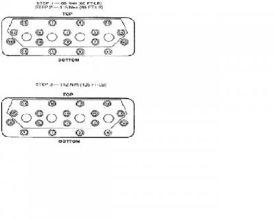

 )
)