Insure you have the tools/items listed below before disabling vehicle
Fender covers to protect paint
7/16 inch deep barrel socket 3/8’s drive with ratchet
10 mm six point socket, 3/8’s drive with 3” extension
Tape or clean towels to cover openings
7 mm and ¼ inch six point sockets, ¼ drive with 3” extension
19mm socket, 3/8’s or ½ drive
Center punch 8-10 inches long
Hammer to strike punch and hand impact tool
Hand impact tool, 3/8’s or ½ drive
T15 & T20 TORX bits ¼” drive with ¼” extension 6” long
¼ to 3/8’s and or ½ adapter to hand impact tool
8mm 6point ¼”drive socket
Large standard screw driver bit with 6” adapter for impact tool
Large screwdriver or small pry bar
Pliers
7/16 inch open end wrench
5/8 inch open end wrench
Torque wrench capable of at least 30 pound-feet
RTV silicon sealant
8 mm allen wrench
1. Park vehicle in a suitable work location, set parking brake, place automatic transmissions in park,
manual transmissions in neutral, and open hood.
2. Disconnect both battery negative battery cables.
3. Clean engine if necessary to keep debris and foreign objects from entering engine
4. Place fender cover or protective covering to protect paint and batteries.
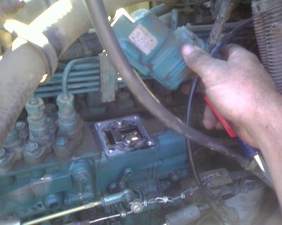
5. Using a 7/16 inch deep barrel socket, loosen lower clamp on upper intake connection hose and slide
lower clamp off of hose and down the steel tube out of the way.
6. Remove the six bolts holding the air intake connection and dipstick tube in place using a 10 mm 6
point socket. NOTE: Observe that these bolts are of different lengths so they can be installed in
correct location during assembly.
7. Remove intake manifold connection and hose as a unit, taking care not to damage gasket. This
gasket can normally be reused however if it is torn, replace with a new gasket, Cummins part number
3913352. NOTE: Hold electrical grid heater in place while lifting the air connection so that the
gasket joint under the grid heater is not disturbed.
8. Cover the air tube and manifold openings with tape or towels to keep foreign objects out.
9. Bend the fuel supply line slightly so as to make access to the break off screw. This option saves some time, eliminates breaking into the fuel line, and make engine restart more quickly.
10. Next remove front passenger side AFC housing break off screw. NOTE: This screw is a factory
break off screw with rounded head and no screw driver, allen head or TORX slot. Use a hand
impact tool with a 6 inch long ¼” extension and a T15 TORX bit to remove this screw. A center
punch may be required to start a hole in the center of this screw. Set the hand impact tool in the
removal position (counter clockwise) and use light hammer taps on the impact tool to loosen this
screw. Tap progressively harder on the impact tool until the screw loosens. This method of removal
forms a TORX shape into the screw allowing it to be reinstalled later with the T15 TORX bit. In
some cases the hole in the top of this screw is too large for the T15 bit thus use the T20 TORX bit.
There is usually a lock washer and flat washer under each of these screws. OPTIONAL: A sharp
chisel can be used to remove the break off screw by making a notch in the outside diameter of the
head, then applying a tangential force with light blows to the chisel counterclockwise to remove the
screw.
11. Use hand impact tool and a 8mm socket to remove the two driver side AFC screws.
12. Use the hand impact tool with large standard screw driver bit to remove the rear passenger side AFC
screw.
13. Pry the fuel shutdown solenoid bracket away from the AFC housing using a larger screwdriver. This bracket only needs to move about 3/8” for clearance.
14. Lift AFC housing, moving it out of the way toward the rear of the engine. The boost pressure line
need not be disconnected. NOTE: Some engines have a metal rather than a plastic boost line
between the engine intake to the AFC housing, in this case the boost line should be disconnected.
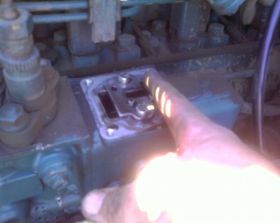
15. Loosen the 2 screws on the fuel plate, sliding the torque curve(fuel) plate as far forward as possible. Some people say it makes more hp when it's .030 or .060" from full forward.
16. Tighten the two torque plate screws and hand tighten as tight as possible with a normal
large screw driver.
17. Be sure that the AFC housing seal is in its groove (it may require a dab of grease or silicon sealant
to hold it in place) then carefully reinstall the AFC housing. Do NOT force the housing into
place, rather insure that the tang on the bottom of the housing fits in the slot in the torque curve
plate. Wiring harnesses, hoses, and the solenoid bracket may need to be moved to get the housing
to drop into its proper location.
18. Move the shutoff solenoid bracket back to its original position so that the AFC housing mounting
screws will pass through the proper holes in the bracket and housing.
19. Install the AFC housing hold down screws loosely in their original locations. NOTE that the AFC housing mounting holes are slotted, slide the housing as far toward
the front of the engine as the slots allow.
20. Tighten the AFC mounting screws as tight as possible with a
normal screw driver, then use the hand impact tool to turn each screw and additional 1/8 to ¼
turn.
21. The AFC housing to boost pressure line fitting may need to be loosened slightly using a 5/8 inch open end wrench for good alignment of the hose. Tighten the two hose clamps loosened in step 8 using a 7
mm socket. NOTE: Reinstall the boost pressure line if it was removed in step 14.
22. Remove the duct tape or towels from the previously covered openings, reinstall the air connection
gasket and the air intake connection, starting the rubber hose on the air intake tube first, then
rotating the connection into position.
23. Clean debris from threads of air connection bolts, then place a small amount of RTV sealer
sparsely on the first ¾ inch of threads, reinstall bolts to their original position and tighten to 18 lb-
ft using a 10mm six point socket and suitable torque wrench.
24. Reinstall lower air connection hose clamp and tighten hand tight, do NOT strip threads on clamp
bolt. Check the other seven air circuit clamps at this time to insure the four hoses and eight
clamps are not leaking air
25. Remove fender and battery cover, lights, tools etc. , and reconnect battery cables.
26. Start Engine and check for leaks.
27. Test drive the vehicle. It should now have much more power
and quicker acceleration. Observe acceleration rate and smoke.
If vehicle is still slow to accelerate or has too much smoke,
adjust the AFC setting as required. To adjust, remove the large
plug on top of the AFC housing using an 8 mm
allen wrench. Take care not to loose the sealing washer under
the plug. Removing the plug exposes a star wheel which
changes the quickness of fueling response to boost. If
acceleration is weak with minimal smoke, rotate top of the star
wheel toward the engine a few revolutions. If vehicle has heavy
black smoke on initial acceleration, rotate top of star wheel away
from engine a few revolutions. Reinstall large plug with sealing
washer and test drive vehicle again. It may take repeated
attempts to get this adjustment set. If heavy smoke is still
encountered with star wheel moved completely to rear position,
go back to step 19, loosen AFC housing and slide it rearward a
1/16 inch, retighten and test again. Repeat unit desired results
occur.