Fuel system schematic

pickupman

Registered User
Joined
Oct 24, 2013
Posts
333
Reaction score
9
Location
Crestline, California
Does anyone have a fuel system schematic for our trucks? A couple years ago I found a pdf somewhere on the internet that looked like it came from the factory service manual that when into detail about the fuel system, but I can't find it anywhere. I already have the portion of the service manual that pertains to the engine, so if anyone knows what I'm talking about and has that, please pm me.
 

idiabuse

Full Access Member
Joined
Oct 15, 2005
Posts
1,242
Reaction score
5
Location
Princeton Fl
I got so tired of that sorry ass system that Ford selected to deliver fuel to the IDI, I had to make my own, just a waste of time them tiny lines and vents and mechanical pumps and routing, just everything they touched was horrible.

Sorry for the rant, that was I how I felt just before I ripped both tanks out to start a whole new cake.

that was 8 years ago.
 

pickupman

Registered User
Joined
Oct 24, 2013
Posts
333
Reaction score
9
Location
Crestline, California
I know how you feel. With my truck the PO put in 2 aux side saddle tanks controlled by 2 manual valves. I'm sure you can imagine the mess of fuel hoses underneath the truck. Before I start the process of tracking down an air inrusion I have come up with some type of diagram for how I think everything is routed so I don't drive myself insane. Once I do figure out what the problem is, there is going to be some major simplification done by me. ;Sweet
 

icanfixall

Official GMM hand model
Joined
Apr 10, 2005
Posts
25,858
Reaction score
681
Location
West coast
Sorry guys but the oem fuel system appears to be a simple system. First off we have a mechanical lift pump that sucks fuel very well feeding the supply and return system. BTW the return system is a lube and cooling loop back to the tank we are using at the time. About 85% of the fuel sucked forwards returns to the tank. There is a fuel tank switching valve. It has 2 supply lines to it from the tanks. It also has 2 return lines from the tanks. Now it has only one supply line leaving the switch. Returning from the engine it has only one line entering the switch. Really simple. Very little fuel actually gets into the engine thru the injection pump. The filters have a return line with a orifice check valve that only flows air and fuel out back to the tanks thru the return lines. Please ad to this if I missed something. I'm no expert.
 

pickupman

Registered User
Joined
Oct 24, 2013
Posts
333
Reaction score
9
Location
Crestline, California
I realize that the fuel system is not overly complicated per say, but I was just hoping to see if anyone had that schematic I was referring to. The schematic I saw included the wiring diagrams for the selector valve and sending units, that was one reason I was hoping that someone might have it, because the PO installed sending units in each of the aux tanks, and I'm curious to figure out how it's wired and if it's different from the stock configuration. In the cab, there's actually a switch that will trigger the fuel gauge to read off either the regular tanks or the aux tanks. Since I've never used the aux tanks, I have no idea if this even works. Anyways I'm the kind of person who if I have and an overview of what I am going to be looking at and what to expect, I do a lot better than trying to figure it out.
 

pickupman

Registered User
Joined
Oct 24, 2013
Posts
333
Reaction score
9
Location
Crestline, California
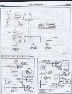
So this is a diagram I came up with of my fuel system:
You must be registered for see images attach


I guess the fuel system isn't complicated after making a diagram of it, but with all the hoses going everywhere it sure feels that way. As the diagram shows, after the tank selector valve, there are 2 manual selector valves, 1 for the supply side and 1 for return side. These are both located in the cab near the driver side seat.

After spending some time underneath the truck, I can see that some of the fuel line looks like it needs to be replaced. One thing I noticed is that in addition to the normal rubber hoses, there is somewhat harder almost like plastic tubing of some sort. I don't know if that is how it came from the factory or was added by the PO, but I cannot figure out what it would be there instead of regular hose. It looks like in some places it was used to "patch" hose together, but some places it looks like it is just there as part of the OEM fuel system.

One concern I had is replacing the return hose coming from the back of the engine, it looks like it runs close to the exhaust. Though the exhaust has heat wrap on it, the existing hose, looks to be the harder plastic type, so if I were to replace that with normal rubber hose, would the heat from the exhaust create a problem there?

BTW, I plan to remove the 2 aux tanks, mainly because I have never used them, and don't want to, they are both rusty on the outside and I don't even want to know what is in them. This should help simplify the fuel system somewhat, it will be way easier to diagnose my fuel supply issues I'm having.
 

pickupman

Registered User
Joined
Oct 24, 2013
Posts
333
Reaction score
9
Location
Crestline, California
For anyone that might find this useful, I actually found the document that I was referring to, it can be found at the following line: http://www.garagenet.biz/tanks&lines.pdf

It looks like this was taken from the factory service manual and I know that it's not part of the "Diesel Engine Supplement" pdf that is available on the web. It goes over the entire diesel fuel system on the suction side of the lift pump. It looks like it has a lot of useful info.
 

opusd2

Full Access Member
Joined
Jun 17, 2008
Posts
1,528
Reaction score
5
Location
BFE, WI
I can't tell you how much trouble this system has been for me. I'm on my second selector valve which helped, until the -20 temps slowed progress. Now, it's the F*&*&ing FSV again!

I'm so damn frustrated (not only by this). I'm tempted to go TOTAL REDNECK ENGINEERING
 

pickupman

Registered User
Joined
Oct 24, 2013
Posts
333
Reaction score
9
Location
Crestline, California
I can't tell you how much trouble this system has been for me. I'm on my second selector valve which helped, until the -20 temps slowed progress. Now, it's the F*&*&ing FSV again!

I'm so damn frustrated (not only by this). I'm tempted to go TOTAL REDNECK ENGINEERING

I guess whatever works right? Maybe you could try manual selector valves mounted in the cab. Like I mentioned earlier in the thread, the PO installed those for the aux tanks. I guess the only problem with that kind of setup is you can't control which tank the fuel gauge is reading from unless you were to install your own fuel gauges. BTW in that .pdf link I posted yesterday there are some diagnostic procedures for the FSV, maybe that can be of some use.
 
Top