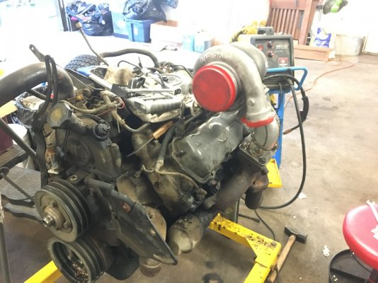
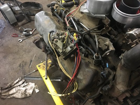
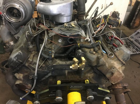
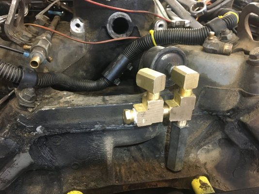
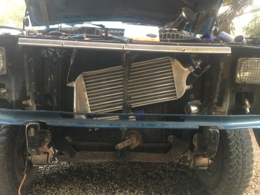
So I am in the works with available time and resources of building up a turbo'ed, bored 6.9L with studs. I've posted in another thread on what I have as far as turbo kit goes.
(
https://www.oilburners.net/threads/rotomaster.39084/#post-1051719)
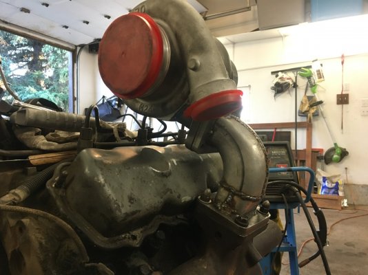
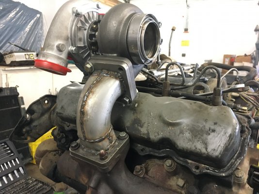
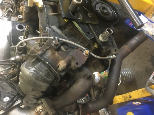
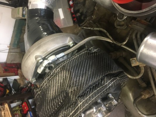
The original turbo was in fair shape save for a pin hole in the hot side and in the end out of curiosity, I wrecked it as I was taking it apart. So there in I did some research on the forums for Turbo IDI information and I picked out this turbo off of eBay.
You must be registered for see images attach
The price dropped considerably after I had made my purchase.
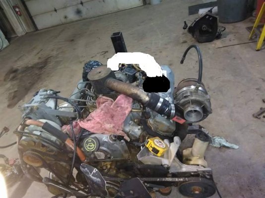
You must be registered for see images attach
In case the pictures don't post...
Cold side: A/R 0.70
Inducer 66.6mm Exducer 84mm
Hot Side: A/R 0.96
Inducer 74mm Exducer 64.5mm
I forget now what all that I looked up and learned before I picked this turbo and flow charts were hard to find that were accurate. I think I was doing a comparison and basing it off of the specifications of the factory turbos that I was able to find accurate information on here. And this one was bigger from what I could tell but I am unsure as to determining what more this turbo could do compared to a factory turbo.
So now to someone who has the knowledge I would like to ask, hopefully with the information provided where does this turbo land as far as operating range and potential output for a rebuilt .040 over bore 6.9L? Not any specific power number really.