7.3L IDI Ford Diesel Truck
Glow Plug Controller Bypass Wiring
As Explained by Adam Clark (Diezel_Cowboy)
First off, let me give a description of the controller. The controller consists of a four post automotive starter type relay that is bolted to a small rectangular black box. It is located near the firewall on top of the passenger side valve cover, and it has a black vented cover to protect it.(See Figure 2) Connecting the black box and the relay is a flat metal resistor, or the slinky looking thing you see facing the front of the truck. The little black box contains a small electrical circuit board that has been sprinkled with a non conductive material that looks like sand, and then sealed completely with some kind of polyurethane. If you turn the controller upside down you will see what I am describing. There are a total of six wires coming out of the black box. (See Figure 1 below.)
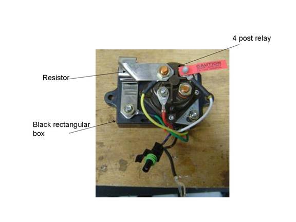
Figure 1 Picture of glow plug controller removed from truck.
OK, now let me try to explain in a round about way how the controller works. The basis of its operation is the monitoring of resistance in the glow plug circuit. Assuming that all the wires in the circuit are good and not rubbed through the insulation in any spots, there are just a couple things that change the resistance of the circuit. The first thing that changes the resistance in the circuit, and the thing that the controller was designed to look for is the heating of the glow plugs. As the plugs heat up their resistance increases, this holds true for any wire or metal with current flowing through it. When the resistance reaches a certain level the controller knows that it should stop sending power to the plugs because they are hot enough for starting. The second thing that causes the resistance of the system to change is burnt out glow plugs or good plugs with a higher resistance. If there are 1 or more glow plugs burnt out then the controller sees a higher resistance in the circuit. Because of this higher resistance, you guessed it, the controller thinks that the plugs are hot enough to start, even though they are not, and it will short cycle or not cycle at all. Remember we are assuming that the wiring in the circuit is in good shape, because a shorted wire will also change the resistance and cause the controller to think that the plugs are hot enough to start when they are not.
Here is where the problem lies with the factory controller logic. It only takes one burnt out plug to handicap the system into thinking that the plugs are hot enough to start. This is because unlike our brains the controller only thinks about one thing………resistance. It does, however, get some input from a temperature sensor located near the water pump, but this sensor only tells it if the truck is hot or not, it doesn’t tell it the source of the resistance in the system. Therefore, the resistance in the circuit is the controller’s only way of knowing how long to supply power to the plugs.
Before you bypass the system you want to make sure that the truck will start in cold weather. Therefore, you should check and replace any bad glow plugs. To check the plugs simply pull the cap off of the plugs and hook a test light to the Positive (+) terminal of one of the batteries. Now touch the test light probe to the top of the plug, if the light comes on the plug is good, if the light doesn’t come on then the plug should be replaced. I would recommend that you use Beru (Motorcraft) plugs since the Autolight brand is known to swell and break off. I would also recommend that before you even begin changing plugs you have a ¼ inch ratchet with at least 12” worth of extensions, a ¼ inch universal joint, a ¼ inch deep well 3/8 socket, and a pair of 45 degree angled tip, extra long needle nose pliers, and an extendable magnet pick up tool. These tools will make changing the plugs and taking the caps on and off a lot easier, especially if your truck has a factory or aftermarket turbo charger. Beer is optional but I wouldn’t recommend getting too shaky until you have checked and replaced the two glow plugs nearest the turbo, since it takes a steady hand to lower them into place with a magnet!
OK, now that you have checked the glow plugs and replaced the bad ones, let me get down to business explaining how to wire up the controller so that it is controlled by a button in the cab rather than resistance of the circuit.
The first step is to remove the cover from the glow plug controller, to do so just squeeze the sides of the cover and pull upward exposing the relay and the black box mentioned earlier. (See Figure 2&3 below)
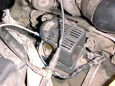
Figure 2 This is the glow plug controller w/ cover.
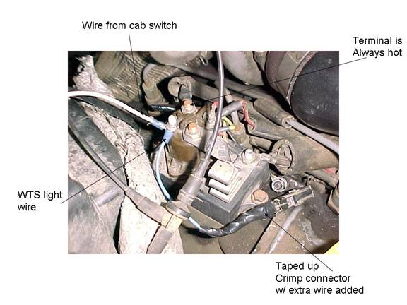
Figure 3 This is the controller w/cover removed.
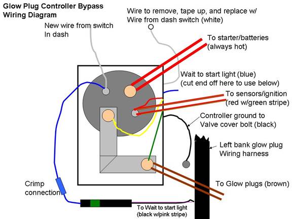
Be careful not to touch any tools from metal parts to the big terminal on the driver side (see Figure 3 above or diagram) since this terminal is always hot. If you are uncomfortable with this wire being hot or are a little shaky, then I recommend that you disconnect the batteries before going any further. I knew you were shaky………so jew disconnect the batteries? OK good, the next step is to locate, remove, and tape up the end of the white wire that is bolted to the small terminal of the relay closest to the firewall of the truck.(See Figure 1 and diagram) Just tape it with electrical tape and position it out of the way of things that might rub the insulation of the wire. This is where you need to decide if you would like the Wait To Start (WTS) light in the dash to light up only when you press the button. If you do continue with the next step involving the blue wire, if you don’t care about the WTS light then disregard any talk about the blue wire.
I knew you would decide to have the WTS light on while pressing the button. Locate the blue wire coming out of the black box of the controller; it should have a fancy black and green automotive connector attached to it.(See Figure 1 and diagram) To make things easier go ahead and unplug the connector. This wire and connector will control the WTS light. Now cut the blue wire near the black box, but be careful to leave enough wire out of the box so it can be taped or capped off somehow. You also need to make sure that enough of the blue wire is still attached to the connector to strip back and add a length of wire to. So you got the blue wire out, and taped up the end coming out of the black box. Now you need to add about a 5 inch piece of wire to the connector using solder or a crimp connector, also you need to add a round terminal to the end opposite the connector that will fit around the small relay post that you removed the white wire from.(See Figure 3 above and diagram) Once that is done you can tape up the connections and plug the connector back into the truck where you unplugged it earlier. Next run a wire, preferably 16 gauge or heavier (I used 12 gauge since it is what I had on hand) from the cab where you are planning on mounting your switch to the controller. It will need a round end crimped or soldered on the end to attach to the small terminal of the relay where you removed the white wire earlier. Once you have the wire for the switch run so that it will not burn or rub on anything, you can hook it and the WTS light wire up to the small relay terminal where the white wire was and bolt both wires down to that terminal. (See Figure 3 above and diagram)
The switch that you choose can be any automotive MOMENTARY switch. A momentary switch will only be on if you physically hold the button. This provides a safety for the system so that the switch isn’t accidentally left on. If left on for over 15 seconds your glow plugs will burn out. You can mount it anywhere in the cab where there is room to house the switch and where it is easy to reach the button. I mounted mine in the dash, just to the right of the ignition.(See Figure 4 below) The switch I bought was a 60 amp momentary automotive switch; I also found a 15 amp which would have worked just as well.
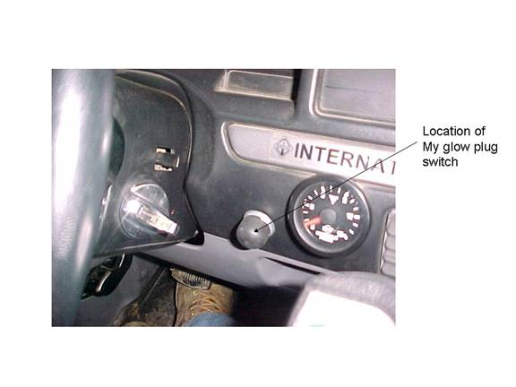
Figure 4 Location on dash where I chose to mount the glow plug switch
Now that we got the switch and one wire run to it from the controller, it is time to hook up the other wire to the switch. The other side of the switch (switch should have 2 terminals) will be wired to a good ground. I ran a wire from mine down to the frame and crimped a round connector on to it. (See Figure 5) The frame is probably the best ground. I would recommend keeping the wire shorter rather than longer, and there are plenty of holes in the frame that aren’t really used where the wire can be bolted, so do not drill a new hole! Make sure that you clean the spot of the frame where you want to bolt the wire. You may need to wire brush it to remove the rust before bolting the wire to the frame.
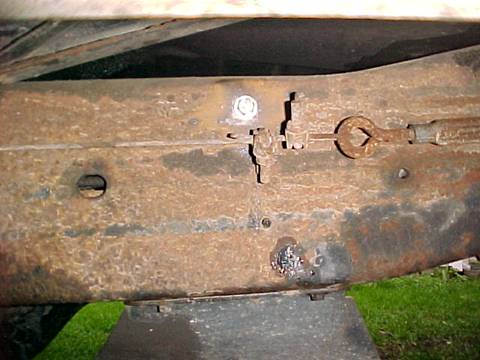
Figure 5 The shiny bolt is where I grounded the one wire going to the switch, the hole in the frame was already there, notice the transmission skid pan below for exact location. Note the wire is on the inside of the frame the picture shows the outside of the frame.
OK, so you got the wire run from the switch and bolted to the frame, now if you haven’t already done so attach each of the wires, the one from the frame, and the one from the controller to a separate post of the switch. It doesn’t matter which one goes where just so long as you connect each of them to their own post. Make sure you’ve got all your tools cleaned up, put the black cover back over the glow plug controller, and hook the batteries back up. You’re done with the installation! No more controller controlling your glow plugs……now you are in control!
To operate your new system, simply turn the key to the on position and push the button. Only hold the button for 5-10 seconds as this is usually enough to start the truck. If it isn’t enough let rest for several seconds, and try again for 5-10 seconds. If you hold the button for longer than 15-20 seconds at a time you risk burning out the glow plugs, since they were only designed for shorter 5-10 second bursts. If you chose to wire up the WTS light wire to the switch terminal you should see the WTS light come on when you press the button. If your glow plugs are in good working order you should also notice your amp/battery gauge needle pull to the left when you push the button. Both the light and the amp gauge are good indicators of what your system is doing and if it is working right. Now you can sit back and enjoy knowing that your truck will start this winter and that you are in control………oh and finish the rest of the beer from earlier!
I would like to thank Kennyd and the other oilburners members who gave me enough knowledge to do this project myself and understand this system enough to write this article!