Moderators note: Please see the end of this thread for updated information. Do NOT rely on the below alone.
The following article was put together by Bobby aka turbo69 and covers the checking and reseting of the FIPL.
Many thanks to Bobby for contributing and we hope that someone somewhere out there benefits from this article.
Fuel Injection Pump Lever (FIPL or TPS) Check and reset procedures.
The FIPL is a fundamental part of the operating system of the E4OD transmission. It aids the Transmission Electronic Control Assembly in determining proper shift points in relation to throttle position and allows the computer to determine both WOT for downshifts and idle position for TC lock and unlock.
Resetting or replacement of the FIPL can solve many of the problematic shifting issues with the E4OD trasmission mated to the 7.3L IDI's.
Below are simplified procedures that can be used to adjust/reset the FIPL.
Hook up the negative lead of the volt meter to the battery ground and the positiove lead to the center GY/W ( grey/white wire which is the FIPL signal wire, I use a paper clip up the side of the wire in the connector. The FIPL must be attached to the wiring harness. Engine low idle speed must be set to specs prior to adjusting the FIPL.
Engine off key on........
With a warm engine, key on, engine off measure the voltage at the GY/W wire, if adjustment is required loosen either the bracket with bolts or just use the slack in the Torx screw holes. Now gently rotate the FIPL until you get some where between 1.05V and 1.1V. then tighten the torx screws or bolts which ever you loosened ensuring no movement of volt setting . Rotate the throttle lever to WOT see if you get 3.8 V but not more than 4.3 V.
The FIPL mounting bracket can be moved but ensure it is centered for a good rotation. Any adjustment should be made by only rotating the FIPL. If a new FIPL is required, check tang engagement as you take off the old FIPL and then make sure that the tangs in the new FIPL engage the throttle lever properly.
The closed throttle voltage: 1.1 V, .........wide open throttle voltage: minimum of 3.8 V but not more than 4.3 V.
DIESEL FIPL SENSOR INFO
DATE 1992
REASON
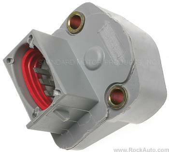
Early Black FIPL has High Failure Rate
RECOMMENDATION
Always replace the black colored early FIPL or any colored FIPL having 60 thousand or more miles, with the late gray colored FIPL.
PART NUMBER
F2TZ-9B989-C
The following article was put together by Bobby aka turbo69 and covers the checking and reseting of the FIPL.
Many thanks to Bobby for contributing and we hope that someone somewhere out there benefits from this article.
Fuel Injection Pump Lever (FIPL or TPS) Check and reset procedures.
The FIPL is a fundamental part of the operating system of the E4OD transmission. It aids the Transmission Electronic Control Assembly in determining proper shift points in relation to throttle position and allows the computer to determine both WOT for downshifts and idle position for TC lock and unlock.
Resetting or replacement of the FIPL can solve many of the problematic shifting issues with the E4OD trasmission mated to the 7.3L IDI's.
Below are simplified procedures that can be used to adjust/reset the FIPL.
Hook up the negative lead of the volt meter to the battery ground and the positiove lead to the center GY/W ( grey/white wire which is the FIPL signal wire, I use a paper clip up the side of the wire in the connector. The FIPL must be attached to the wiring harness. Engine low idle speed must be set to specs prior to adjusting the FIPL.
Engine off key on........
With a warm engine, key on, engine off measure the voltage at the GY/W wire, if adjustment is required loosen either the bracket with bolts or just use the slack in the Torx screw holes. Now gently rotate the FIPL until you get some where between 1.05V and 1.1V. then tighten the torx screws or bolts which ever you loosened ensuring no movement of volt setting . Rotate the throttle lever to WOT see if you get 3.8 V but not more than 4.3 V.
The FIPL mounting bracket can be moved but ensure it is centered for a good rotation. Any adjustment should be made by only rotating the FIPL. If a new FIPL is required, check tang engagement as you take off the old FIPL and then make sure that the tangs in the new FIPL engage the throttle lever properly.
The closed throttle voltage: 1.1 V, .........wide open throttle voltage: minimum of 3.8 V but not more than 4.3 V.
DIESEL FIPL SENSOR INFO
DATE 1992
REASON
Early Black FIPL has High Failure Rate
RECOMMENDATION
Always replace the black colored early FIPL or any colored FIPL having 60 thousand or more miles, with the late gray colored FIPL.
PART NUMBER
F2TZ-9B989-C
Last edited by a moderator: