Hairbrained idea for cheap timing meter/onboard display

BDCarrillo

Supporting Member
Supporting Member
Joined
Jul 19, 2014
Posts
1,245
Reaction score
10
Location
Abilene TX
Yard work, honey-do's, 3G alternator upgrade, and replace ignition switch on the guinea pig truck. And 4th of July party prep. Hold yer... caribou. I'll solder a tab on the sensor and install it in the truck. Should clear up the lumpy idle once all the injectors are firing at the right time.
 

G. Mann

Full Access Member
Joined
Apr 13, 2007
Posts
927
Reaction score
86
Location
Phoenix, AZ
While you are dinking with a crank sensor.. a question.
Why not pick up a signal off the Tach drive sensor? It counts RPM which is gear driven directly off the crank.
And.. it's already setting in place.
 

BDCarrillo

Supporting Member
Supporting Member
Joined
Jul 19, 2014
Posts
1,245
Reaction score
10
Location
Abilene TX
For rpm, yes you could use the tach sensor (as Hertz, since the stock sensor outputs AC), for timing, no... we need that zero mark on the harmonic balancer to figure out where in the cycle the injector event occurs.
 

BDCarrillo

Supporting Member
Supporting Member
Joined
Jul 19, 2014
Posts
1,245
Reaction score
10
Location
Abilene TX
You must be registered for see images attach

This is an individual pulse, as tested on a truck with the positive probe on the factory timing sensor, attached via soldered tab. Ground was the injector line nearby.

You must be registered for see images attach

A set of pulses.

Sooo... looks usable, with a more pronounced negative spike compared to positive. The peaks seemed to travel from a negative high to a positive high. I'll have to do some research on that and see if it's piezo crystal harmonics or sensor fatigue.

Next step will be cleaning and filtering that signal on the hardware/electronics side.
 

Attachments

  • DSC_0009.JPG
    DSC_0009.JPG
    725.7 KB · Views: 60

laserjock

Almost there...
Supporting Member
Joined
Nov 20, 2012
Posts
8,841
Reaction score
3,129
Location
Maryland
I bet it's real. It's probably the line expanding with the plunger compressing the fuel, dumping the fuel and the fine structure is probably a little ring down. Cool. I'd love to see what a standard line clamp sees in comparison.

Really cool man!
 

BDCarrillo

Supporting Member
Supporting Member
Joined
Jul 19, 2014
Posts
1,245
Reaction score
10
Location
Abilene TX
Thingamajiggy has a decent chance. Just need to clean up that signal and then figure out the mag pickup. I pulled a front cover out of the parts pile to spec a sensor.

UPDATE:
Looks like I can set up a simple conditioning filter with a cap, diode, and resistor. I oughta have those in my parts bin, and can tinker with it tonight. Ironically it's a very similar conditioner to the boost sensor in my other thread (which is also a piezo-based sensor, go figure).
 
Last edited:

BDCarrillo

Supporting Member
Supporting Member
Joined
Jul 19, 2014
Posts
1,245
Reaction score
10
Location
Abilene TX
Why cant you mount a probe in the timing hole itself for mag prove then set in offset of 20deg?

That's the plan! Just have to take measurements and find a sensor that'll fit with the proper output.

I'm looking at a NO inductance sensor... give it 12v off the vehicle, mayyybe use an NPN sensor to pull a 5v PNP fet to get the output arduino friendly. Ideal scenario would be to generate a positive pulse everytime the timing mark goes by, but I know it'll likely result in a dip in an inductance sensor output (based on tach sensor testing). That's where a threshold would have to be set so the NPN could pull down a PNP 5v fet.

Or I keep it all positive voltage and see what the output is like from a PNP NO sensor. Use a voltage divider to get it to that 0-5v friendly range and have arduino watch for the voltage drop as the timing mark whizzes by. Surely it'll have a fairly steady voltage until that mark goes by.

Another random thought... at idle, say 10 rps, the timing mark on the harmonic balancer is moving at about 282 inches per second, and if the mark is (generously) 1/8" wide, it's only 1/226th the size of the wheel, so from start of groove to end of groove it'd take .0044 to pass by the sensor. The chip on the Trinket can run at a maximum of 16khz, so about 0.000625s per cycle, not counting instructions being executed... so yeah, as long as the code re-runs fast enough we should still have good resolution on the RPM. I was worried the balancer may outrun the microcontroller!

UPDATE
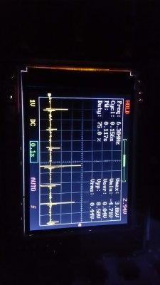
Well my first filter didn't work. A little zener diode, 1uf cap, and 1k resistor wiped out the signal. Without the diode it was down to a few mv. I need to take another approach, maybe half wave rectification with a pass filter to wipe out the low end noise.

UPDATE2
Bridge rectifier inbound Saturday. It'll get all the juice that the stock sensor puts out onto the positive side of the spectrum and then I can re-eval the waveform and maybe run a high pass filter to isolate the peaks.

UPDATE3
Test mule is down... banks air box being disposed of and turbo plumbing being reworked. Got a full and half bridge rectifiers in, and soldered them up on test boards with alligator leads.
 
Last edited:

BDCarrillo

Supporting Member
Supporting Member
Joined
Jul 19, 2014
Posts
1,245
Reaction score
10
Location
Abilene TX
Well that's as much as I could clean it up, even with a full bridge rectifier. It's like twanging a guitar string, the frequency of each injection looks like a sound wave. The main problem, is that each "twang" of the injector hits at different parts of the natural harmonic of the piezo crystal. Constructive and destructive interference plays havoc, thus the odd peaks/valleys... but they are at the right time, and respond to changes in RPM.

Thar she be:
You must be registered for see images attach


There's a thin chance I could bump up that measly 2v signal to trigger a timing light with a big ol' op-amp. Note that I'm getting 2v now because it's run through a full bridge rectifier.

Disclaimer: I ain't no electronical engineer, wrangling ones and zeros.
 
Last edited:

laserjock

Almost there...
Supporting Member
Joined
Nov 20, 2012
Posts
8,841
Reaction score
3,129
Location
Maryland
I bet you could integrate your way out of it. I think that's probably what the timing meters do. I bet they sample and integrate because I doubt they update the screen every 2 milliseconds. Seems like if you could integrate for a couple seconds, you could average that out enough to be fine. You are just looking for the delta between the injector and the mag probe. Maybe just set a threshold so you are just looking at the bigger peaks? Something else I'm sure you have thought of but technically if you are using #1, you only want every other crank signal. 1 of the pulses will be 180 out.

This is pretty neat. I want to get back to playing with my electronic widgets again.
 

BDCarrillo

Supporting Member
Supporting Member
Joined
Jul 19, 2014
Posts
1,245
Reaction score
10
Location
Abilene TX
I did think about software filtering it out. Reject samples when two crank rotations are registered without an injection being detected.

Dump the Delta's in an array and average over say 10 samples.

The hard part will be sending an interrupt, since 2v isn't enough to drive a digital pin high. Maybe a voltage doubler or multiplier then limiting to 5v to make arduino happy. I could also loop an analogread above 1.5v, but that's slower.

For simplicity, driving a timing light will be my first objective, then I'll go digital. A cheapo homebrew timing light adapter probably has more utility for all of us here. Just need to pump that output from the stock sensor into a coil to trigger an inductive pickup... sounds easy, right?
 

BDCarrillo

Supporting Member
Supporting Member
Joined
Jul 19, 2014
Posts
1,245
Reaction score
10
Location
Abilene TX
I'll look into those, thanks!

I implemented a 10 sample averaging routine in my boost/purpose gauge, so I know it's do-able. Basically loop through a 10 position array dropping a sensor read in each position, then I take a running average of the whole thing and convert it to an usable output.

Next swag at a solution will be a simple transformer coil. May have to fart around with my timing light to figure out a detection threshold for it.

UPDATE
Haven't forgotten about this project. Picked up some magnet wire yesterday and will have to scrounge up something to use as a transformer core. I'm thinking that I can wind a small coil to boost the stock sensor output to trigger a regular timing light. We'll see...

On the digital timing meter idea, it's feasible to use the current 2v output with all the gaps and discard time data where an injection event isn't registered. The main issue with the digital side is the inability to feed it raw AC output from the stock sensor
 
Last edited:
Top