IP gear cover oil leak at valley pan

tbrumm

Full Access Member
Joined
Mar 24, 2012
Posts
1,224
Reaction score
187
Location
Richland Center, WI
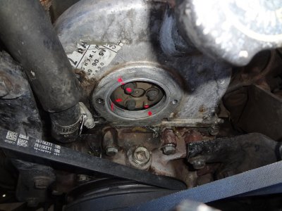
Quite a while back, Mel posted up a pic in thread of a way to "clamp" the IP gear to the cover to keep it form moving and thereby be able to remove the cover with the pump. I thought I had that thread saved in my subscriptions, but I'll be darned if I can find. I ran a search and could not find it either. I know Gary was also posting in that thread. The reason I ask is this: The IP gear cover on my truck has always seeped a little bit of oil down into that "pocket" between the front of the engine and the right side of the water pump. It was a slow seepage and I would just wipe up the little puddle of oil once in a while. Now, it is leaking enough that it is running into the valley pan and then out the drain bolt and onto the starter. I was hoping not to have to mess with this until I buy my Baby Moose next year, but the leak is getting worse. I checked the bolts on the IP gear cover and they are tight. So, if anybody can point me toward this previous thread, or chime in if they have resealed the gear cover, that would be much appreciated. Is there a gasket under the cover, or is it just RTV as I suspect? Thanks! Todd
 

riotwarrior

Supporting Member
Supporting Member
Joined
Sep 19, 2006
Posts
14,778
Reaction score
482
Location
Cawston BC. Canada
don't quote me on this....but IIRC remove the two IP GEAR lemon shaped cover plate retaining bolts undo the 3 12 pt bolts and take LONGER bolts and thread them through the lemon shaped cover bolt holes to press against the IP gear....IIRC that's what he was talking about.....

Good luck.
 

tbrumm

Full Access Member
Joined
Mar 24, 2012
Posts
1,224
Reaction score
187
Location
Richland Center, WI
Thanks for the reply, Al. Now that you explained it that way, that kind of jogged my memory and I think you are right, that was the way Mel described it. I will have to wait to do this until I have a block of time to devote to this and be careful and take my time. So, "surgically clean" the parts and RTV only and no gasket?
 

riotwarrior

Supporting Member
Supporting Member
Joined
Sep 19, 2006
Posts
14,778
Reaction score
482
Location
Cawston BC. Canada
Thanks for the reply, Al. Now that you explained it that way, that kind of jogged my memory and I think you are right, that was the way Mel described it. I will have to wait to do this until I have a block of time to devote to this and be careful and take my time. So, "surgically clean" the parts and RTV only and no gasket?

Yes surgically clean...if you wouldn't let an infant lick it...it's NOT CLEAN enough....as far as I know it's RTV only however I could be wrong...hopefully someone will chime in with that fact.
 

icanfixall

Official GMM hand model
Joined
Apr 10, 2005
Posts
25,858
Reaction score
672
Location
West coast
Its RTV only on this gasket area. In the aluminum cover is a recess area thats got to be cleaned out of the oem RTV or you wont get a good leak proof seal. If I were to repair a leak here I would not do it like Mel suggested but what he posted about is a good way. Its just the idea you can't see the timing marks match up. My pic shows that all the gears will be like when your at tdc number one cylinder. See the injection pump drive pin location at around 4 o clock. Then notice the drive bolts locations. Now having the engine timed correctly like this you can remove the gear from the pump and draw a line from the "Y" timing mark to the top of the gear. Now with this done as you set the gear to the cam gear you can't mess up with the gear tooth timing because of the line you have. Just use a 90 degree tri square off the top of the timing cover plate to insure you are straight up and down on the gear. Another idea talked about years ago was remove the injection pump gear but make sure your at tdc number one. Then count up both sides of the gear 17 teeth from the "Y" tooth. Draw a line across the gear at the 17 tooth count. Now set the gear in the cam and make sure the line is parallel with the top of the meatal timing gear cover plate that the water pump bolts to. Test this one tooth either way to make you feel good your doing it right. There are many ways of doing this leak repair.
You must be registered for see images attach
 

icanfixall

Official GMM hand model
Joined
Apr 10, 2005
Posts
25,858
Reaction score
672
Location
West coast
BTW if you click on my pics the picture is blown up really nicely so the marks are easier to see. One can even count the injection gear teeth up both sides the 17 count too. BTW the cam gear has the same amount of teeth the injection pump gear has and the crank gear has exactly half that amount of teeth.
 

tbrumm

Full Access Member
Joined
Mar 24, 2012
Posts
1,224
Reaction score
187
Location
Richland Center, WI
Thanks for your reply, Gary. I am not looking forward to doing this, but the oil leaking onto the valley pan is making me crazy. I am hoping Mel will chime in as well with his thoughts too. Sure don't want to have to pull the front cover off! I suppose whichever way I decide to go about this, I will take some pics and post them to maybe help someone else in the future. Todd
 

icanfixall

Official GMM hand model
Joined
Apr 10, 2005
Posts
25,858
Reaction score
672
Location
West coast
Look at my pics again. If you have the engine at # 1 tdc you can see what the injection pump gear will look like sitting correctly on the cam gear. What I don't have a pic of is the location on the damper mark and the timing tab. But I can tell you the short fat probe location center line is the top dead center mark. May have to clean off some road dirt to see it but its there just the same. So looking at the pic what you do is mark the injection pump gear from the "Y" mark at the bottom all the way up to the top of the gear. Then a square is used based off the top of the engine timing cover plate to insur the gear is timed correctly. Move the gear back and forwards one or two teeth to see what the line looks like. You can't mess up doing it this way. What scares me about doing the gear removal any other way is when the gear is connected to the pump in the aluminum housing you have no real way of insuring the gear is aligned properly. your hoping and guessing and I feel thats not what needs to be done this deep in the engine
 

Knuckledragger

blowing chunks and grabbing porcelain
Joined
Nov 7, 2008
Posts
2,340
Reaction score
234
Location
Payson, AZ
If you have to take it off as a unit, I agree with Al in post#2. The long (5/16-18) bolts should have a point ground on the tip to create a good purchase on the IP gear and you should be OK to take it off. It is still much preferred to take the IP off of the housing first and leave the gear in place on top of the engine. Then you don't have to guess where the "Y" mark lines up.

Clean as described, RTV to seal and don't start it for a day to let the RTV set up correctly.
 

bbjordan

Snow Monkey
Joined
Feb 24, 2011
Posts
1,421
Reaction score
393
Location
Ashern Manitoba
I say take it apart the recommended way; separating the IP and the gear. Make a timing mark on the IP & housing first or just take a picture of an exisiting one. Line up the bottom end with timing mark. You'll know that it's not 180* out by looking at the dowel pin in the timing gear. It will be in the 4 o'clock position. The inspection plate will need to be off for this obviously. You can then mark your gear with paint/scribe. It'll be easier to put it back together right. The advantage of this is that it is WAY easier to clean the aluminum housing. And you want to clean it. You will want to clean the block and the valley pan too.

M2CW
 

riotwarrior

Supporting Member
Supporting Member
Joined
Sep 19, 2006
Posts
14,778
Reaction score
482
Location
Cawston BC. Canada
one note I should add...

REMOVE the IP from the package and then bolt through lemon cover to IP gear and remove gear cover....that' makes it less likely to have issues ...IF you have an old IP with NO LINES bolt in with one or two bolts this will stop gear from falling out....

Try to get the IP LINED UP as GARY's image shows as well this will really make this a simple remove IP/install bare IP/ bolt gear in place with lemon cover bolts/ remove cover carefully, reverse to install...

JM3CW
 

FoolhardyIDI

Full Access Member
Joined
Sep 5, 2014
Posts
376
Reaction score
42
Location
Arizona
When I pulled my IP and top cover I marked the gear with a red paint pen. Took two test fits to get it put back just right.
 

Attachments

  • 014.JPG
    014.JPG
    265.3 KB · Views: 94

Agnem

Using the Force!
Supporting Member
Joined
Jan 10, 2005
Posts
17,067
Reaction score
374
Location
Delta, PA
One method I described at a rally a couple of years ago, was to use a tool I had made (and handed some out to those present). Basically what it amounted to was a pointer that bolted to one of the IP drive shaft bolts and rode along on the circumference of the gear housing opening. All you had to do was scribe a line, and make sure that when you bolted it back on, that the line matched. The gears have a very fine tooth count in the relative scheme of things, because of the diameter, and it is very easy to end up one tooth off. You need a highly accurate way to mark the position. Locking the gear to the housing with a longer bolt is possible, but you run the risk of bending something if you make it too tight.
 

TahoeTom

Supporting Member
Supporting Member
Joined
May 19, 2010
Posts
749
Reaction score
113
Location
S. Lake Tahoe, CA
You must be registered for see images attach

I used a straight edge across the top of the block to scribe a line on the IP gear. The gear will rock to one side or the other so it may not be square to the timing marks. I checked putting it one tooth off and it was easy to see the line wasn't parallel to the block.
 
Last edited:

icanfixall

Official GMM hand model
Joined
Apr 10, 2005
Posts
25,858
Reaction score
672
Location
West coast
You must be registered for see images attach

I used a straight edge across the top of the block to scribe a line on the IP gear. The gear will rock to one side or the other so it may not be square to the timing marks. I checked putting it one tooth off and it was easy to see the line wasn't parallel to the block.

Marking a line from the "Y" to the top of the gear would have been an easier way to show correct gear teeth timing. Or counting 17 teeth up each side of the gear from the "Y" mark and making a line.
 
Top