Perhaps you have been considering the application of a turbocharger to your 1983 to 1994 International Harvester/Navistar powered Ford F series pickup? This article will attempt to give you some insight as to what is involved and the difficulty or ease in which the installation is accomplished.
Preface:
The 6.9 and 7.3 liter “IDI” engine Ford used in the F and E series trucks prior to the introduction of the “Powerstroke” engine introduced in 1994, is ideally suited for the application of a turbo. There are presently three turbocharger systems on the market for the beloved IDI; which can be purchased for application on a stock, normally aspirated engine, of which all production IDI’s were until the availability of the optional factory turbo in the 1993 model year. This article will focus on the “Pulse Turbo” product from Hypermax. The Banks and ATS systems, as well as the similar but different Hypermax turbo for E series engines are beyond the scope of this article, as is the discussion of the virtues of wastegated or non-wastegated turbo systems. We hope that the pictures and story will help you with your installation if you choose to follow the same path we did.
 Photo
courtesy of Hypermax
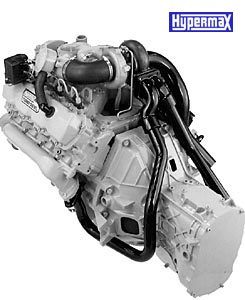
Photo
courtesy of Hypermax
Introduction:
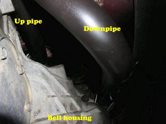
The Hypermax Pulse turbo is unique in the industry, as it features twin up pipes from the exhaust manifolds to the specially designed split turbine housing. The unit is non-wastegated for maximum boost and low backpressure. The installation is as simple as mounting the turbo, plumbing the oil lines, and connecting the exhaust pipes. A feat which would be incredibly easy, were it not for the fact that the engine is in a truck! I would estimate installation time on an engine mounted in an open bay, or on an engine stand to be approximately 1 hour. With the engine in the truck, figure about 8 times that! The installation is the same for all models of IDI’s, with minor differences in how to deal with the glow plug wiring harness. On the 6.9, the wiring harness can be left as is. On the 7.3, the glow plug controller needs to be relocated. Our installation was performed with a strange mix of Hypermax parts. Our kit was bought used, and began life as a non-pulse system, but was upgraded to a pulse due to difficulties with parts compatibility stemming from the fact that our truck has a manual transmission. Be aware that the shape of the up pipes will vary between an automatic or manual transmission, but the installation is essentially the same.
Installation:
Begin by removing the air cleaner completely and covering the intake. I recommend putting a plastic cling film over the intake, and then securing it with duct tape. You may find yourself leaning on this a lot, so make the protection sturdy. Note that the wire screen can be easily bent, so if you do lean on it, place a board over it so your weight can be supported by the bolt hole and the edge of the intake mouth. I like to place a rag over this also. On a 7.3 like ours, take the glow plug harness all the way off. This makes it easier to prevent damage from any thrashing about. Unbolt the glow plug controller and remove it with the wiring. Remove the factory CDR located behind the intake, and install the rubber plug in the intake according to the Hypermax instructions. The valley pan grommet will be dealt with later. Remove the factory Y pipe from the exhaust system. Also disconnect the throttle cable bracket from the intake, and remove the throttle and cruise cables if so equipped from the injection pump.
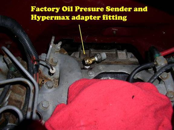
Next, remove the factory oil pressure sender from the top of the block, and insert the brass fitting provided in the kit. Note that early model 6.9 powered trucks had a remote oil sender attached with a hose. If this is the way yours is, you will remove the hose and attach the sender directly. Adjust the angle of the fitting to that approximately shown in the photo above. Insert the factory oil pressure sender in the side of the fitting. Use a pipe sealing compound such as Teflon tape on the threads to ensure a leak free future. Concerns about loss of electrical ground using this method have thus far proved unwarranted, but be aware that this potential exists. If you find you have no oil pressure when you first start the engine after the project is complete, remember this fact and ground the sender housing manually to check and see if this is the issue.
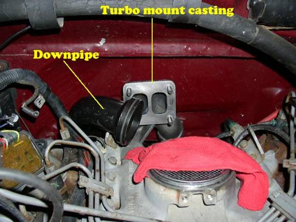
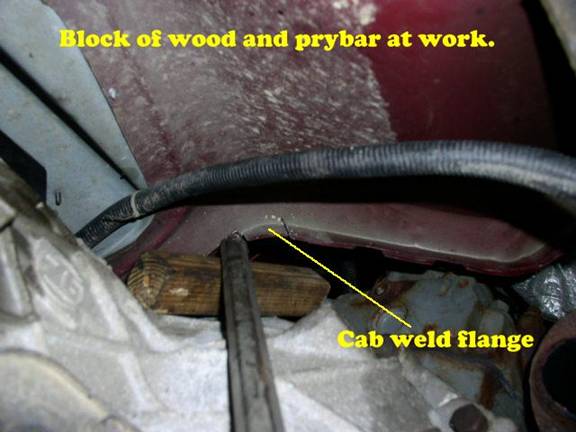
Next, fit the downpipe into the space between the engine and body. This is where it starts to get fun. Take note of the cab weld flange. It will need to be bent up flush with the bottom of the cab. Various methods have been employed by different people to accomplish this. The method I used was to take a Sawzall and cut slits into the flange to section it into easily bendable pieces. Use some kind of pry bar or hammer to bend the flange out of the way. This process will need to be repeated for each pipe you install, so get a good idea of where the clearances need to be created and work on them throughout the project as needed. Attach the turbo mount casting to the rear of the passenger side head. You may need to remove a ground wire and reattach it after the casting is installed. Test fit the left and right side up pipes, creating cab weld flange clearance as needed.
By this point, you may have several hours into the project. As simple as these steps sound, nothing ever comes apart or behaves the way you wish it would. Just getting the up pipes to fit without touching the cab can take hours of frustration and contortion.
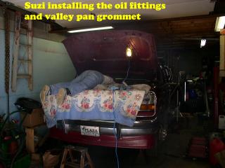

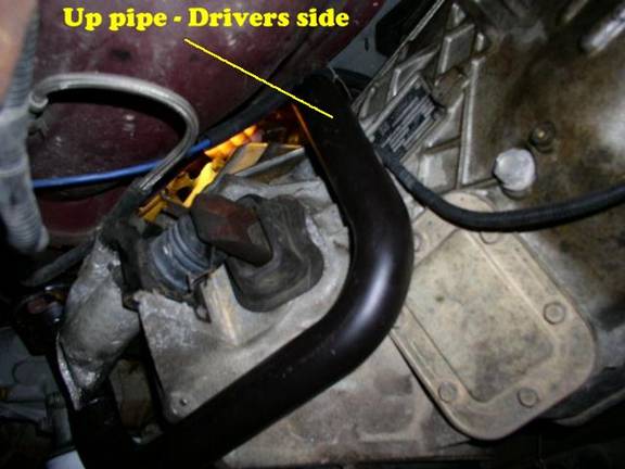
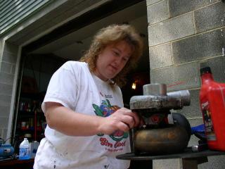
Above, we see our intrepid turbo installer in the assumed position. There are really only two positions you will be familiar with. The pain in the gut, and the pain in the back! How long you are in each, is up to you. The task is simple. Install the up pipes, connecting the bottom end to the exhaust manifold with the flange provided, and then secure the top end of the pipe to the turbo mount casting using the small bolts included in the kit. There are no gaskets used in the piping, as the up pipes utilize a unique sealing system that relies on the heat of the engine to expand the pipe and seal it to the mount. Do both the left and right sides. Leave the downpipe loose until after the turbo is installed. The driver’s side pipe rests virtually on top of the transmission and bell housing, making photography impossible, and creating great difficulty in clearancing the cab weld flange. A 2” body lift would make this a non-issue, so if you are considering that kind of modification to your vehicle, I’d highly recommend doing it before hand, as that mod alone will cut the time this project takes at least in half. Another option is removing the transmission and bell housing, but unless you are doing this work out of necessity, I don’t think it will save you any time. Another thing that would have helped in our case, is a new set of body mounts. I think our bushings are sagging a bit, which seems common with crew cab trucks, creating even less space for the install. If you have a crew cab, and you’re considering replacing your body mount bushings, that would be another great task to complete. You could even interrupt the body mount replacement to jack the cab up a little and complete the turbo install before lowering it down on the new mounts. Be all that as it may, we did this job without doing any of that stuff, and you can too. It’s just a benefit that you have our wisdom from experience to consider.
Note that I had previously removed the exhaust shielding from this truck. The shielding is a light metal that maintains an air space behind it to insulate the floor of the truck from the heat of the exhaust. In the moderate climate of the northeast, the exhaust radiant heat has never been a problem. The shield runs the full length of the truck from the cab weld flange to the rear axle. Removing this also helps greatly with immunity to vibration from inadequate clearances. Above and below are pictures of the same location, before and after.
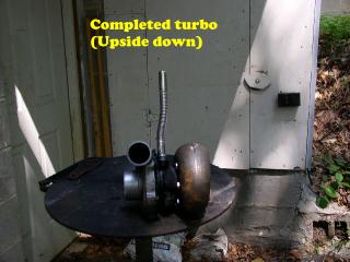
As I had mentioned before, our turbo was used, and required us to swap the exhaust housings. You will be fortunate that you don’t have to bother with this part, but as an aside, I had to use a torch to cut off the bolts and free the housing. Below we see Suzi assembling the completed turbo.
Prepare the valley pan by cleaning it in the area of the CDR grommet. Remove the old grommet and do the oil flow test. Depending on the year and condition of your IDI, your valley pan may or may not need additional oil flow capacity. Using thin motor oil such as 5w-30, attempt to pour a quart of oil through a funnel into the valley pan CDR drain hole. If the oil does not overflow and run all over the valley pan, then your valley pan is modern and doesn’t need modification. If however, the hole quickly fills up and overflows like ours did, you will need to modify it. Using an awl and a hammer, punch a dozen holes into the baffle visible through the CDR hole. You must use an awl instead of a drill, as this method will not displace metal shavings into the engine. Do the oil test again, and when you are satisfied that the oil flow capability is good, install the grommet into the valley pan provided with the Hypermax kit.
Attach the oil drain tube to the turbo with the provided bolts and gasket. Next, insert the oil drain tube into the rubber valley pan grommet previously installed, and push the tube in while lining up the turbo mounting studs on the turbo mount casting, with the exhaust housing mounting flange. Be sure to hang the metal turbo to cast mount gasket on the studs before you do this. I had a devil of a time with this part, as even with the drain tube lubricated with oil, I couldn’t get it to go into the grommet without pushing the grommet into the valley pan. Several attempts and a lot of frustration led me to dismount the turbo drain from the turbo, and install just the turbo drain into the grommet, and then the turbo onto the drain and mount casting at the same time. I hope you don’t have to do it this way, as it greatly increases the pain in the gut due to the extensive time fiddling with fasteners. Once you have the turbo and drain in place, fasten the turbo in place with the 4 nuts and lock washers provided. You will find a variety of tools are needed to tighten these. A socket with extension is handy, as is a selection of combination wrenches.
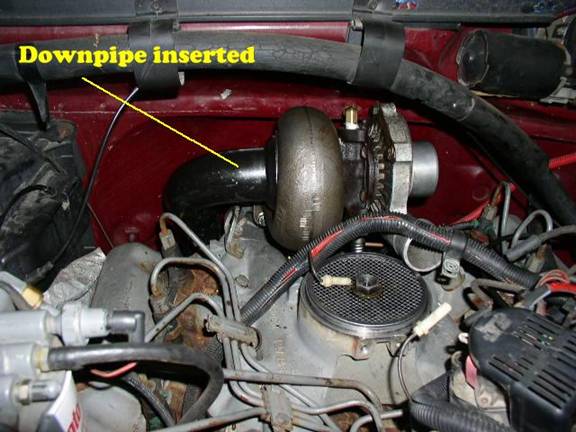
Next, fit the downpipe into the exhaust housing. There is nothing to hold the pipe in the housing, as there is a tab on the downpipe which fastens to the turbo mount casting with two bolts. This holds the pipe in the exhaust housing. A ring, similar to a piston ring, is in a grove around the downpipe flange, and this must be compressed with a flat bladed screwdriver to get the downpipe flange to mate fully. I recommend putting some graphite anti-seize compound on this ring and flange during assembly to ensure it comes apart in the future if necessary. Your stock exhaust will mount up to the downpipe with a short piece of pipe Hypermax provides. You may have to cut off a small portion of your factory Y pipe to facilitate the connection. I have a custom exhaust anyway, so I just used my own pipe and clamps to connect the downpipe to the rest of my exhaust system. Hypermax provides a nice band clamp to connect the downpipe to the adapter pipe. In the above picture, we see the turbo and downpipe fully mounted. Yes, I know the intake is open and uncovered. Do as I say, not as I do! LOL! That and the glow plug harness is obviously in the way. Like I was saying…
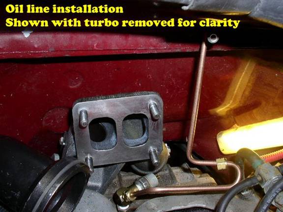
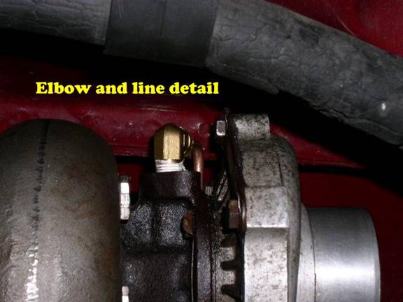
Next, install the oil line between the brass adapter in the block, and the elbow in the top of the turbo. The line is shown below to clarify the routing. Yes, the nut on the bottom is fun to tighten as you contort to do this task. You may also have to install the elbow on the top of the turbo. Make sure all these parts are clean inside as you assemble them.
Now you are ready to install the intake hat. The intake hat is a casting which fits over the intake manifold opening. It is held in place with a single bolt which replaces the bolt which held the air cleaner on. A short silicone boot connects the compressor output to the intake hat. Two hose clamps are used to fasten the boot between the two. Make sure you arrange the hose clamps for easy tightening. Lubricate the large rubber O-ring provided with some motor oil, and slip it into the intake hat casting. This O-ring is the gasket which seals the intake hat to the intake manifold. You may find it necessary to rotate as you lower the intake hat to get it to both seat properly on the manifold, and also to engage the silicone boot simultaneously.
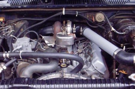
The photo below, while not on this project truck, shows the intake hat and boot more clearly. Note that the air intake is in a different home made configuration.
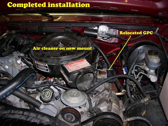
Your Hypermax pulse turbo kit will come with a casting that allows you to use your factory air cleaner with the turbo. The one we used is the old style casting from the pre-pulse turbo kit that we started out with. For that reason, I have not detailed that piece. Suffice it to say, it mounts to the intake manifold and is connected to the turbo with a 90 degree rubber boot. I personally prefer an open element type filter, which you can easily adapt with a little creativity, and parts from www.airflowonline.com. Before putting the casting on, re-route your glow plug harness if needed according to the Hypermax directions. A plate is provided to mount the glow plug controller over the drivers side valve cover. Note that Hypermax provides parts to facilitate re-use of the CDR valve, mounting it on the provided casting, and then requiring you to drill a hole in your valve cover and install a fitting and hose. I strongly recommend against this method. Instead, purchase a PN 94042-00 IP gear cover adaptor from Gale Banks Engineering, and use a different hose to connect the CDR valve to it. There is much less oil splash in the IP gear case than what is present in the valve cover, and lower oil consumption and less chance of leakage will be gained. I also simplify things by doing away with the CDR completely, instead setting up a road draft tube and plugging the orifice in the intake.
Another nice touch, is to insulate your throttle cable with a piece of heat resistant fiberglass wrap, such as that sold at speed shops to protect the starter motor from exhaust header heat. I slide this under the turbo (shiny side up towards the exhaust housing), and over the cables and any wires, and wire tie the heat shield in place.
There are two locations in your Hypermax turbo installation where you will want to add some instrumentation. On the passenger side up pipe, you will find a fitting that is threaded for a pyrometer probe. Most exhaust gas temperature gauge kits come with an industry standard fitting that will thread into this opening. If you do not locate your EGT probe here, you will need to plug the hole with a pipe plug of the proper size. The second location is in the intake hat. Here you will find an orifice for a boost gauge. I recommend the “Manifold Pressure Gauge” from ISSPro. This gauge is available in a 0 to 15 range, and is a perfect match for this turbo. Standard “boost” gauges often end in higher values, rendering much of the scale unusable. The intake hat will receive the plastic hose and fittings provided in the ISSPro kit. Once again, if you do not install anything here, you will need to plug the orifice.
Once you have everything all put together and secure, remove the forward wire from the top of the injection pump to disable starting of the engine, and crank the engine for 15 seconds to build oil pressure and pump oil into the turbo. Once you believe you have oil there, reconnect the wire and start the engine. Allow it to idle and check for any leaks. If you have a boost gauge attached, do not expect to see any boost, either at idle, or by increasing the engine speed. A turbo only produces boost when the engine is under load, so once your sure you are leak free, head for the open road and find a nice steep hill.
A note on injection pump settings: The whole idea behind adding a turbo, is to get more air into the engine to burn more fuel. More air + more fuel = more power. So, it is common to turn up the fuel setting on your injection pump when adding a turbo. I found on this truck, that I got the extra power I wanted without turning up my fuel. Pulling my 30’ 7000lb RV, I could go up hills in the next higher gear, than what I was previously able to do. My EGT’s went down about 300 degrees, and my fuel mileage went up slightly. The turbo makes about 8 pounds of boost. If you choose to turn up your pump, you will need to make sure you have a pyrometer installed, and that you do not exceed 1250 degrees. However, you may want to try your stock setting for a while, just to see what you can do.
We hope that you benefit from this article, and that your own case of “red belly” includes a smile.