High Idle Manual Override
by Ron Butts (Dsl_Dog_Catcher)


This simple electrical modification applies to 1983 through 1994 Ford Diesel trucks and vans equipped with 6.9 or 7.3 liter IDI power, and is for anyone that may have the need to get a few extra rpms without having to manually adjust the idle set screw on your injector pump to sustain an elevated engine idle speed.


A few possible uses for such a modification:

·         May be to operate a 120 volt AC power inverter

·         Prevent battery drain with extra 12 volt lighting on your rig

·         Help warm up the engine faster in the colder climate areas

·         Reduce the chances of “wet stacking”*


As you may or may not know, diesel engines have a large cooling system, which can take on a lot of heat but can dissipate it very quickly while idling. Extended idling of such engines will cause the cooling system to keep the engine cool enough that it may not maintain an adequate operating temperature. This of course depends on the ambient temperature or climate where you live. Over time reduced combustion temperatures can harm the engine and reduce engine life.


In my case, I chose to do the modification due to the fact that there are times when my truck may have to remain idling for a lengthy time period. The fact that I could decrease my truck engine life concerned me and would like to be able to maintain it and get the most use out of it as we all would like to do. Also, due to the harsh Michigan winters here, it’s nice to have a little extra heat in the cab, and a high idle facilitates this quite nicely.


Well to get things started you will need a few basic tools and parts to complete the task:

·         Wire cutter/crimper

·         Soldering iron and solder

·         Drill with an assortment of bits

·         Screw drivers Phillips head and flat blade

·         Needle nose pliers

·         Heat gun or similar device for heating shrink tubing

·         12’ of 16 gauge wire

·         Electrical tape

·         Heat shrink tubing with an adhesive liner to accommodate up to 14 gauge wire

·         Flexible wire protective conduit, sometimes called split loom tubing

·         Standard lighted 12 volt toggle switch

·         Assorted wire end connectors

·         1 diode part # 1N4001 or equivalent, available from Radio Shack part number 276-1101. See http://www.radioshack.com/product/index.jsp?productId=2036268&cp=&kw=1n4001&parentPage=search
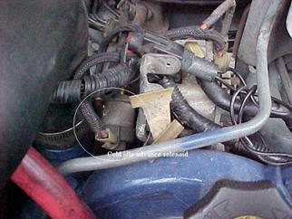


To get an idea of what is going to be done, here is a basic diagram drawn to show what the current cold idle advance system wiring looks like before the modification. Special thanks to Argve (Travis Pruitt) for the initial schematic which I have redrawn for this article.


Here is a basic diagram to show the system modification once completed. The diode will prohibit the activation of the timing advance system once voltage is supplied by the newly installed toggle switch.


12 volt switched


To begin the process, remove the keys from the ignition and disconnect the batteries. (Editors note:  Disconnecting the negative cables from both batteries is sufficient)  Keep safety first as you will be working with the electrical system. Next you will need to locate the wiring to the cold idle advance solenoid and remove the connector from the solenoid itself. The wires are encased within a black rubberized mesh material. Remove about 5” worth of this material starting from the connector to expose the wires. There will be 2 red wires covered with this shielding. I cut off about a 3” piece of the wires from the end of connector. This will keep the length to a minimum to avoid too much wiring around the front of the injector pump. I then removed the 3” pieces of the wire from the connector and spread the connector wire retainer as this connector will be need to be reused for the modification.


Next begins the diode installation. With the soldering iron warmed up, take the 2 red wires that have had the shielding removed, and strip off ½” of the wire insulation and twist them together. After doing that, go ahead and solder these 2 wires together. To reduce the chances of heat damage to the diode, you can tin up the end of the diode and solder it to the already soldered red wires. Make sure that the diode direction is correct. The diode will be black with a silver band at one end. The silver banded end of the diode will be on the outside of the wiring and should not be soldered into the red wires at this time.  See the photo below. I must apologize at this time, as the camera would not focus properly on the diode due to the small target area, and the camera kept focusing on the intake.

Once you have the diode soldered to the wires and it has cooled, just give the diode a little pull to make sure the connection is solid.  Your solder should look shiny and smooth, and not rough, as this would indicate a cold solder joint likely to fail. Another option in lieu of soldering would be to use a butt connector as an alternative. Probably would not be my first choice due to connector longevity with the amount of vibration that a diesel engine produces. The soldered joints will last much longer in my opinion.


Next you will need that spool of wire and will take about a 2” piece and cut it off. Strip both ends about ½” and you will need to solder one end of this piece of wire to the diode. The side of the diode that you should be soldering this wire to should have the silver band leading towards this new piece of wire.  Once again solder the wire first then solder the diode to the wire to avoid heat damage to the diode. Once that solder joint has cooled, give it a slight pull to make sure it has a good connection.


The diode soldered into place.


At this point you will need to slip on a piece of the heat shrink wrap tubing over the diode that  should be long enough to cover at least 1” over the ends of the solder joints to help seal things up. The extra length will also accommodate for the tubing as it shrinks down. Heat it up until it has completely and evenly formed around the diode assembly. I then took a second piece, slightly longer that the first piece of heat shrink tubing. Placing it over the freshly covered diode assembly and heated it over top the first piece. This gives the assembly some rigidity to keep the diode from being damaged from normal wear and tear.

What you will do next is run a length of wire from your desired toggle switch location, I chose the dash out through the firewall and up over the drivers side of the intake to the area of the injection pump. Do not cut it at this point, as you will need to connect it to the toggle switch. At this time also it would be a good idea to tuck this new wire into some split loom tubing to protect it from being damaged. I had utilized the factory split loom tubing for the glow plug wiring as it keeps things along the top of the engine neat and tidy. Once you have the wire all tucked away up close to the injection pump, go ahead and cut it off. Strip ½” of the wire insulation off the end of the wire, and take the wire that has been soldered to the diode and about a 3” piece of heat shrink tubing over the 2 wires and crimp the end back into the factory connector.

You now can heat the final piece of shrink-wrap down over the 2 wires, as close to the connector as possible, and should give you a good solid hold so the wires cannot separate from each other or from the connector, as seen below.


Now you can go ahead and reconnect the connector to the idle advance solenoid and cover the remainder of the open wires with the split loom tubing.


The finished look.


Final installation will be to hook the wiring up to the toggle switch and locate your fused power source of choice.  You want to make sure that the power source DOES turn off with the key and is not a direct link to the battery. Doing so could cause the solenoid to fail if left on indefinitely, and may also eventually drain the batteries.


Now for the test. Go ahead and reconnect the batteries and start the truck up with the switch turned off. Let the truck warm up so the cold idle advance system disengages.


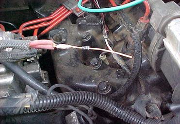
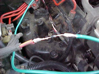
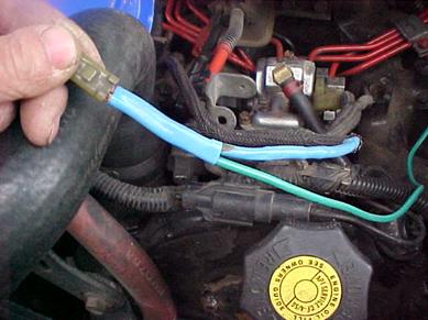
Now you can flip the toggle switch to the on position and depress the accelerator pedal to where the solenoid will hold the throttle to the adjusted setting. If all is connected properly, the solenoid should now be able to be manually controlled at the flip of a switch. I have even set the toggle to the on position during a cold start so it keeps the idle elevated without having to stay near the truck.  The mod is a pretty simple setup and can have several uses for the happy trucker.


Definitions/Terminology


 *Wet stacking is a term used to defined a variety of potential ailments such as the washing of the cylinders with diesel fuel, lack of proper ring sealing due to lower combustion temperatures, valve guide contamination, or “slobber” accumulating in the exhaust valve area, exhaust manifold and exhaust system due to idling the engine for extended periods of time at reduced combustion temperatures.

Reference http://www.intellidog.com/dieselmann/b_smoke9.htm for an example of this discussion.