Instrument Cluster Project
By: Paul Trosen
Screen Name: 6point9diesel
Written For: www.oilburners.net
Introduction:
This document describes the steps I went through to modify the existing instrument cluster for an 80-86 Ford diesel pickup. The reason for the modification is because I am adding a boost and pyrometer gauge, and I don’t like any of the aftermarket options for mounting these gauges (pillar mount, over dash mount, under dash mount). I am also not satisfied with the existing water temp and oil pressure gauge that Ford supplies. The procedure discussed here applies to the 80-86 model Ford pickup (F250 in my case but the F150, F250, F350, Bronco all basically use the same dash. If someone would be interested I believe this modification could be done in much the same way for an early body style or later body style pickup or bronco.
The instrument
Cluster is comprised of several parts.
From front to back they are as follows:
- Wood grain trim piece
- Clear Plastic Cover
- Black Plastic Faceplate
- Gauges
- White Plastic Backing
- Laminated Circuit Board
- Instrument Lights
- Indicator Lights
The parts that you
will need to have on hand to complete this project are the following:
- Sturdy piece of sheet metal
- Hind-sight I would have used 3/16” aluminum…stiff and easy to cut
- Gauges (I’m listing the Auto Meter Model numbers for my gauges. I bought them from Summit Racing: www.summitracing.com)
- Speedometer (Model: 3992)
- Oil Pressure (Model: 3421)
- Water Temperature (Model: 3431)
- Boost/Vacuum (Model: 3301)
- Pyrometer (Model: 3344)
- Fuel (Sending and Receiving) (Gauge Model: 3316, Sender Model: 3262)
- Voltage (Model: 3391)
- Etc
- Adapter To Fit Ford Speedometer Cable Assembly. You can purchase one through VDO to fit a 22mm speedometer (Part #: VDO-200202. Call VDO and verify the thread size. It is advertised for a 5/8” cable fitting, but it doesn’t work.)
- You can make one with the following parts to fit a 5/8” speedometer
- 3/8” female brass flare nut fitting
- Brass/Bronze Bushings (Described in more detail later in this document)
- Speedometer cable kit
- Wire
- Connectors
- Labels (For Wire Connections)
First off I must apologize. I do not have appropriate pictures to show every step of this process. I am writing this after I built my cluster only because I think some of my trials and tribulations may help your project run more smoothly. As with any electrical work to your pickup, disconnect the battery or batteries J as the case may be. Also I completed this project with my steering wheel installed. It will be easier to remove the wood grain trim piece if you remove your steering wheel, but if you turn your trim piece just so, it will slide over the steering column. I had a parts pickup as a backup if I broke anything, but everything went fairly smooth.
Steps:
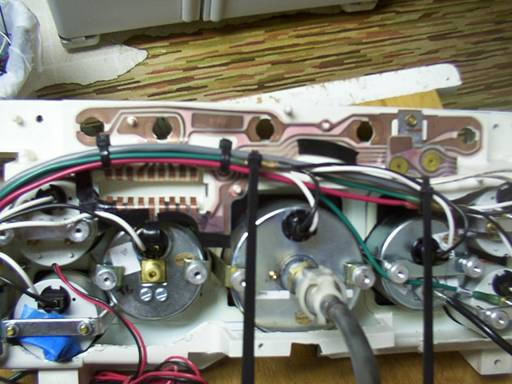
1. Remove instrument cluster assembly from your 80-86 Ford Pickup. It looks like the following:
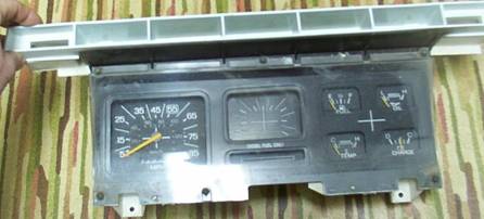
2. Disassemble the cluster so you have the following pieces
a. Clear Plastic Cover
b. Black Plastic Faceplate
c. Gauges
d. White Plastic Backing
e. Laminated Circuit Board
f. Instrument Lights
3. Next you will need to trace out your instrument cluster design on a piece of paper such that it will fit the black plastic faceplate. What I mean by “fit the black plastic faceplate” is outlined in red in the following picture:

If you look at your current instrument cluster assembly you will see how the red line follows the shape of your black plastic faceplate. Keep in mind when you trace out your gauges you will have to leave room for the gauge bezels. For example if you have a 2” gauge the hole required to fit the gauge will be a 2 1/16” hole the bezel will probably be about 2 1/8” to 2 ¼”, so the footprint of the gauge will be
2 1/8” to 2 ¼”.
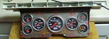
4. It is a good idea at this point to take the paper layout of your cluster and test fit it to see if your setup will work. You can do this by cutting your paper such that it will fit inside your black plastic faceplate (red line on step 3), and installing the fake wood grain trim piece over the top to see if all your gauges will fit inside the instrument cluster opening. Your gauges can go outside the trim piece opening, but you’ll have to make room by cutting the trim piece. I notched the wood grain trim piece on mine to allow the two lower gauges to fit. In the following picture I circled this area in red:

5. Once you are happy with how everything fits on paper you will need to transfer your design on your piece of sheet metal. With this said cutout your sheet metal to your specifications.
6. With the sheet metal cut out, place all your gauges inside and lay your wood grain trim piece over the top. This is just to give you one last chance to eyeball everything up before you start cutting the harder to replace items.
7. Remove your gauges from your sheet metal cutout and place the cutout in position over the top of your black plastic faceplate. Now you will need to cutout any plastic you see in any of the holes. This will allow your gauges to fit through both pieces.
8. Once the plastic material is removed from your black plastic faceplate, place your sheet metal cutout over the top of the faceplate. Now slide all your gauges into the appropriate locations in your cutout to verify that they will fit. Cut any additional material needed to obtain a good fit.
9. Now remove your gauges so you are left with your sheet metal cutout over the top of your black plastic faceplate. You need to drill several holes through the sheet metal cutout to fasten the sheet metal cutout to the black plastic faceplate. I drilled three holes along the top, one on each side and used the existing holes along the bottom. I have circled the hole locations in red in the following picture:
I used stainless #8 machine screws for the new hardware
10. Now take your white plastic backing piece and completely cutout the back. So you just have the sides. This will allow room for your gauges and access to the wiring when all the pieces are joined. It should look something like the following when done:

11. Install your gauges through your sheet metal cutout (which should be fastened to your black plastic faceplate with new and existing hardware). With the gauges installed test fit the assembled black plastic faceplate with your cutout white plastic backing. Remove any material that interferes with the gauges and assemble these two pieces.


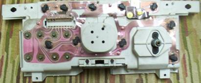
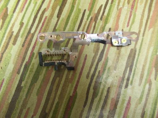
12. Once these two pieces are assembled it is time to modify the original laminated circuit. In my setup I replaced as many gauges as I could with mechanical gauges. I wanted to use the existing wire for the fuel sender, the existing wire for the dimmer circuit, and keep the indicator lights functioning on top. To find the appropriate wire for the fuel sending unit I followed the connection point in the laminated circuit from where the fuel sending unit was back to the connector location. From this I determined that it was the white on yellow wire on the instrument cluster plug/harness. I did the same thing to verify the location of the supply source for the dimmer circuit. I found this to be a red on blue wire. Then I followed all of the copper traces in the laminated circuit to all of the locations for the indicator lights on top. I then removed any traces I didn’t need from the laminated circuit. For the areas that I cut across a copper trace I used electrical tape to cover the edge. This is to prevent any short circuit situations later on. The original laminated circuit looks like the following:

The new laminated circuit looks like the following (note the electrical tape):
13. You can now install your laminated circuit on your white plastic backing:
14. Now you will need to wire your gauges. I set it up as follows:
a. Red: Ignition Circuit +DC (hot when the key switch is in the on position)
b. White: Dimmer Circuit +DC (hot when lights are on and varied with the dash light pot)
c. Green: Chassis Ground
Label everything so you know what’s where later on
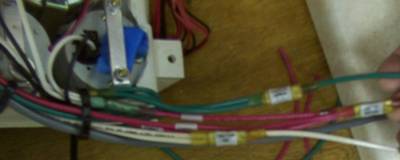
(sorry bad picture, but you can see the labels)
To tie all my wiring together I ran my fuel sender +DC to the white on yellow wire I found in step 12. I ran my dimmer circuit (white wire) to the red on blue wire I found in step 12. I ran my voltmeter +DC and my pyrometer +DC (red wire) to a spare location on my fuse block (use a test light or a voltmeter to find a suitable location). I ran my dimmer circuit –DC, fuel gauge sender –DC, pyrometer –DC, and voltmeter –DC to a good chassis ground. That should be everything. Like I said, I used as many mechanical gauges as I could. If you decide to go with electric gauges, trace out all the existing wires you can to prevent having to run new wires.
15. So that leaves us with that pesky speedometer cable…PITA!! To make your life easier, try to find a speedometer with a 22mm speedometer cable connection. VDO makes a Ford speedometer cable adapter that fits a 22mm (you better verify that this is in fact 22mm) speedometer cable connection. If you do like I did and get a speedometer with the 5/8” connection here’s what I did.
a. Materials you will need: 3/8” flare fitting nut, bronze/brass bushings, universal speedometer cable kit. Purchase the bushings so that they will fit inside one another:
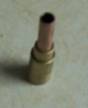
And so the outside bushing will slide into your existing Ford speedometer cable quick connect. You want to get enough bushings so that the inside diameter of your smallest bushing is just large enough for your universal speedometer cable to slide in and out.
b. Slide all of your bushings inside one another So they are flush on one end. On the other end you need to cut the bushings so that there is a lip that holds the flare fitting nut. It will look like the following:
(Note: the protruding bushing just fits inside the flare fitting nut.)
c. Chuck your bushing (all of them together) into a ½” drill so that the flush end of the bushing is sticking out of the end of the drill.
d. Now wrap your drill with a shop rag and chuck it into your bench vise. Do this so that your bushing is facing horizontally. Now turn your drill on and set it so it runs on its’ own.
e. Use a die grinder or a Dremel tool with a small cutoff wheel to cut a groove in your bushing. You will want to do this about 1/8” from the end of the flush end. The groove should be anywhere from 1/16” to 1/8” deep. This groove will be where the Ford Speedometer cable locks in place.
f. Remove your bushing from the drill, and solder the bushings together from the flush end. Make sure you keep the hole in the middle free of solder.
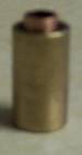
g. Now position your flare fitting nut over the protruding bushing so that it sits flat on the outside bushing. Solder your flare fitting nut from the outside and the inside. When you are done you should have something that looks like this:

(Note: the groove for the speedometer cable is not present on this picture)
f. Test fit the adapter to make sure it slides in and out of the Ford Speedometer cable.
g. Test fit your adapter to the Speedometer. Make sure no rotating parts come in contact with the adapter.
h. With the adapter attached to the Speedometer attach your speedometer cable.

With everything assembled cut your universal speedometer cable to length.
i. Clean out your old speedometer cable housing with brake cleaner. Lubricate with graphite (does not freeze).
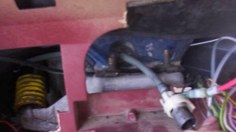
16. I put my speedometer right in the middle of my instrument cluster. Having done it this way I needed to drill a 1” hole in one of the dash supports. After I drilled the hole I installed a grommet and ran my speedometer cable through the hole:
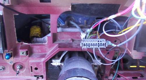
17. With everything done thus far we are ready to bring the cluster out to the pickup. You will need to put your assembly in place and carefully look to see what is interfering behind the assembly. You will need to trim off any plastic that interferes with the installation of your instrument cluster. This took me quite a while. After I was done trimming this is what I had:
18. Once your assembly is sitting in place carefully route you’re new wires so that they are out of the way of any moving parts. Connect any connections that need to be made (electrical connections, speedometer, plumbing).
19. Start your rig and verify everything is working properly.
20. Secure your new assembly using the original hardware.
21. Install the wood grain trim piece over the top of your new assembly.

22. Take it for a spin.
Conclusion:
I am still in the process of getting my rig on the road, so I have not road tested this yet. All my gauges work, but I haven’t been able to test the speedometer. I installed aftermarket fuel sender units that I bought with my fuel gauge (neither of mine worked). I had to modify my tanks/old sender units during this process.
The whole thing would take about two weekends to complete.